Materials Science: Unit I: Crystallography
Crystallography
Definition, Crystal Systems, Crystal Structure, Characteristics
Materials differ from one another in their properties.
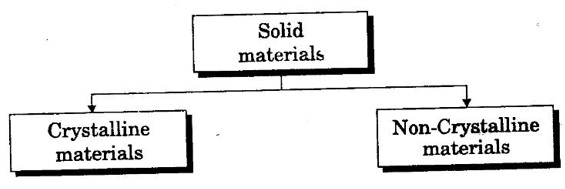
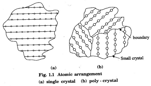
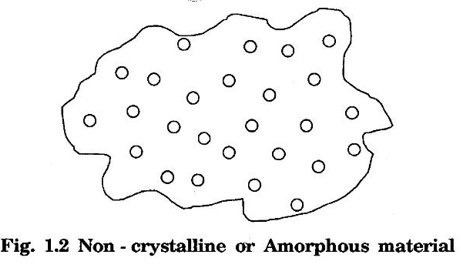
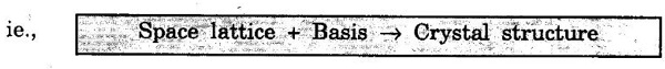
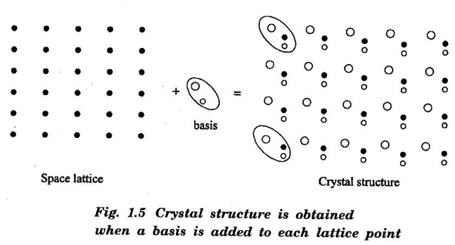
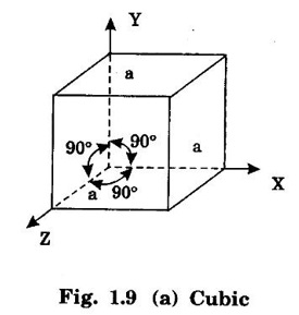
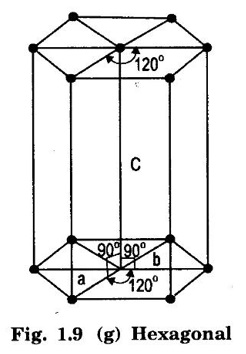
Unit – 1 Crystallography Crystal structures: BCC, FCC and HCP - directions and planes – linear and planar densities – crystal imperfections - edge and screw dislocations - grain and twin boundaries - Burgers vector and elastic strain energy - Slip systems, plastic deformation of materials - Polymorphism - phase changes nucleation and growth - homogeneous and heterogeneous nucleation. Materials differ from one another in their properties. Some solids are brittle, some are ductile, some are malleable, some are strong, some are weak, some are good conductors of heat and electricity, some are bad-conductors of heat and electricity, some are magnetic, some are non-magnetic and so on. The differences in the properties of the various solids are due to their structures. The behaviour of a solid material is related to its crystal structure. From the crystal structure point of view, the solid materials are broadly classified as (i) Crystalline materials and (ii) Non-Crystalline or Amorphous materials (i) Crystalline materials The materials in which the atoms are arranged in a systematic pattern (regular pattern) are known as crystalline materials. In these materials, the arrangement of atoms is in a periodically repeating pattern. Single and Poly Crystalline Materials The crystalline material is either a single crystal or poly - crystal. In single crystal, the entire material consists of only one crystal. (Fig. 1.1 (a)) In poly-crystal material, a collection of many small crystals is separated by well-defined boundaries. (Fig. 1.1 (b)) The atomic arrangements of single crystal and poly - crystal are shown in fig 1.1 (a) and (b). The crystalline materials are made up of either metallic crystals or non-metallic crystals. Example Metallic crystals Iron, copper, silver, aluminium, tungsten, etc. Non-metallic crystals Crystalline carbon, germanium, silicon, crystallized polymers, etc. Amorphous Materials Amorphous means without form. The materials in which atoms are arranged in an irregular (random) fashion are known as non-crystalline or amorphous materials. Example Glass, rubber and plastics. The arrangement of atoms in non- crystalline materials in two dimensions is shown in fig. 1.2. Let us understand some of the important crystallographic terms. Crystal A crystal is a three-dimensional solid which consists of a periodic arrangement of atoms. Crystal structure The arrangement of atoms in a crystal is known as crystal structure. It is the basis for understanding the properties of materials. Crystallography or Crystal physics The branch of physics which deals with the internal structure, properties, external or internal symmetries in a crystal is known as crystallography or crystal physics. Space Lattice A crystal is an array of atoms in three dimensions. As a matter of convenience, these atoms can be associated with a set of imaginary points in space. These points are arranged in such a way that every point has an identical surrounding as any other point in three dimensions and it is known as a space lattice or simply lattice. Lattice is an imaginary geometrical concept. It is a large assembly of points in which each point represents the position and orientation of an atom in the crystal. Note: In 2 dimensions, the arrangement of points is only in 2D (X & Y)]. Space lattice is as an array of points in space to represent atoms in a crystal in which the environment about each point is the same i.e., every point has identical surroundings as that of every other point in the array. The collection of points in two dimensions is shown in fig. 1.3 (a) and (b). It is found that in fig 1.3 (a) the environment (position of neighbouring points) about any two points is same. Hence, it is a 2D lattice. The mathematical representation of a 2D lattice is For example On the other hand, in fig. 1.3 (b) the environment about any two points is not the same. So, it is not a proper lattice. A similar argument is extended to three-dimensional space lattice. For 3D, Lattice points The points in a space lattice are called lattice points (Fig. 1.4). Lattice lines The lattice points are joined with lines as shown in fig. 1.4. These lines are known as lattice lines. Lattice plane A plane containing lattice points is known as lattice plane. (fig. 1.4) Definition The crystal structure is obtained by adding a unit assembly of atoms to each lattice point. This unit assembly is called basis. Explanation A basis may be a single atom or assembly of atoms which is identical in composition, arrangement and orientation. When the basis is repeated in a space lattice with correct periodicity in all three directions, then it gives the actual crystal structure. Therefore, a space lattice combined with a basis gives a crystal structure. The basis combined with lattice points is shown in fig 1.5 in which two atoms (represented by circles of smaller and large radii) are added to one lattice point (represented by a black dot). For many metals, the number of atoms in basis is one (Aluminium and Barium crystals), two or three or move. For example in NaCl and KCl, each basis has two atoms and in CaF2, basis has three atoms. But, for many complicated structures, the basis exceeds more than 1000 atoms. Note A space lattice refers to the geometry of a set of points in space whereas as a crystal structure refers to the actual arrangement of atoms in space. Single Crystals Consider a two-dimensional space lattice as shown in fig. 1.6. It is found that when a parallelogram ABCD is repeated by an integral multiple of vectors The region ABCD is known as unit cell. The choice of the unit cell is not unique. It can be constructed in a number of ways like A'B'C'D' or A′′ B′′ C”D” without affecting the symmetry of the crystal (fig. 1.6). Definition The unit cell is defined as the smallest geometric figure which is repeated in three dimensions to derive the actual crystal structure. The unit cell fully represents the characteristics of the entire crystal. The same principle is extended for a three-dimensional case. A unit cell in three-dimensions is shown fig. 1.7. It is also defined as the smallest volume of a solid from which the entire crystal structure is constructed by translational repetition in three-dimensions. The unit cell is constructed if the distance between two neighbouring lattice points along three directions and angles between them are known. The distance between two neighouring lattice points is the edge of the unit cell. The lengths OA, OB, OC in three axes OX, OY and OZ are the axial lengths or intercepts. (Fig. 1.8) In fig 1.8, the axial lengths OA = a, OB = b and OC = c are known as intercepts a, b and c along three axes. The angles between three intercepts (a, ẞ and y) are called interfacial angles. The three intercepts and three interfacial angles are the lattice parameters of the unit cell. They determine the actual size and shape of the unit cell: (a, b, c) axial lengths, (α, β, γ) - interfacial angles. There are "7" types of crystal systems. They are 1. Cubic 2. Tetragonal 3. Orthorhombic 4. Monoclinic 5. Triclinic 6. Rhombohedral 7. Hexagonal In this crystal system, all the three axial lengths of the unit cell are equal and they are perpendicular to each other (fig. 1.9 [a]). i.e., a = b = c and α = β = γ = 90° Example: Iron, Copper, Sodium Chloride (NaCl), Calcium Fluoride (CaF2). In this system, two axial lengths of the unit cell are equal and third axial length is either longer or shorter (fig. 1.9 [b]). All the three axes are perpendicular to each other. i.e., a = b = c and α = β = γ = 90° Example: White tin, Indium. In this system, three axial lengths of the unit cell are not equal but they are perpendicular to each other. (fig. 1.9 [c]). i.e., a ≠ b ≠ c and α = β = γ = 90° Example: Sulphur, Topaz. In this system, three axial lengths of unit cell are not equal. Two axes are perpendicular to each other and third axis is obliquely inclined (fig. 1.9 [d]). i.e., a ≠ b ≠ c and α = β = 90°, γ ≠ 90° Example: Sodium sulphite (Na2 SO3), Ferrous sulphate (FeSO4). In this system, three axial lengths of unit cell are not equal and all the three axes are inclined obliquely to each other (fig. 1.9 [e]). i.e., a ≠ b ≠ c and α ≠ β ≠ γ ≠ 90° Example: Copper sulphate (CuSO4), Potassium dichromate (K2Cr2O7) In this system, three axial lengths of the unit cell are equal. They are equally inclined to each other at an angle other than 90° (fig. 1.9 [f]). i.e., a = b = c and α = β = γ ≠ 90° Example: Calcite. In this system, two axial lengths of unit cell (say horizontal) are equal and lying in one plane at angle 120° with each other. (fig. 1.9 [g]). The third axial length (say vertical) is either longer or shorter than other two and it is perpendicular to this plane. i.e., a = b ≠ c and α = β = 90°, γ = 120° Example: Quartz, Tourmaline. Bravais showed that there are only 14 possible ways of arranging points in space such that the environment looks same from each point. Thus, there are only 14 types of space lattices which are possibly developed from '7' crystal systems. These 14 types of space lattices are known as Bravais lattices. The lattice can be primitive or non-primitive. A primitive cell is the simplest type of unit cell which contains only one lattice point per unit cell (contains lattice points only at the corners of unit cell). Example: Simple Cubic (SC), Simple Tetragonal The unit cell which contains more than one lattice point is called non- primitive cell. Example: BCC, FCC and HCP contains more than one lattice point per unit cell. If the number of lattice points per unit cell is two (BCC), three and four (FCC), then the unit cell is called doubly primitive, triply primitive and quadruply primitive respectively. It has 3 possible types of arrangements of lattice points. (i) Simple (or primitive) cubic lattice (SC) It has lattice points at all 8 corners of the unit cell as shown in fig. 1.10 (a). (ii) Body-centred cubic (bcc) lattice It has lattice points at all 8 corners of the unit cell and one lattice point at the body centre as shown in fig. 1.10 (a). (iii) Face - centred cubic (fcc) lattice It has lattice points at all 8 corners of the unit cell and one lattice point at each face centre of 6 faces of the cube as shown in fig. 1.10 (a). It has two possible types of lattices. (i) Simple tetragonal lattice It has lattice points at all 8 corners of the unit cell as shown in figure 1.10 (b). (ii) Body-centred tetragonal lattice It has lattice points at all 8 corners of the unit cell and one lattice point at the body centre as shown in fig. 1.10 (b). It has four possible types of lattices. (i) Simple orthorhombic lattice It has lattice points at all 8 corners of the unit cell as shown in fig. 1.10 (c). (ii) Body centred orthorhombic lattice It has lattice points at all 8 corners of the unit cell and one lattice point at the body centre as shown in fig. 1.10 (c). (iii) Face - centred orthorhombic lattice It has lattice points at all 8 corners of the unit cell and one lattice point at the each face centre of the 6 faces of the unit cell as shown in fig. 1.10 (c). (iv) Base - centred orthorhombic lattice It has lattice points at all 8 corners of the unit cell and 2 lattice points each at the centre of two faces (base) opposite to each other as shown in fig. 1.10 (c). It has two possible space lattices. (i) Simple monoclinic lattice It has lattice points at all 8 corners of the unit cell as shown in fig. 1.10 (d) (ii) Base- centred monoclinic lattice It has lattice points at all 8 corners of the unit cell and 2 lattice points each at the centre of two faces (faces of the base) opposite to each other as shown in fig. 1.10 (d) It has only one possible space lattice. Simple Triclinic lattice It has lattice points at all 8 corners of the unit cell as shown in fig. 1.10 (e). It has only one possible space lattice. Simple Rhombohedral lattice It has lattice points at all 8 corners of the unit cell as shown in fig. 1.10 (f) It has only one possible space lattice. Simple Hexagonal lattice It has lattice points at all 12 corners of the hexagonal unit cell and 2 lattice points each at the centre of two hexagonal faces of the unit cell (top and bottom) as shown in fig. 1.10 (g). In fact, it is proved mathematically that there are only 14 independent ways of arranging points in three dimensional space such that each arrangement confirms to the definition of space lattice. The unit cell is characterized by the following parameters: (Assuming one atom to one lattice point) (i) Number of atoms per unit cell (ii) Coordination number (iii) Nearest neighbouring distance (iv) Atomic radius (v) Packing factor (i) Number of atoms per unit cell It is the number of atoms possessed by the unit cell. This is determined by the arrangement of atoms in the unit cell. (ii) Coordination Number (CN) It is is the number of nearest atoms directly surrounding a particular atom in a crystal. The coordination number gives the information about the packing of atoms in a structure. It tells whether the crystal structure is closely packed or loosely packed. If the coordination number is high, then the structure is more closely packed. If it is low, then the structure is loosely packed. (iii) Nearest neighbouring distance (2r) It is the distance between the centres of two nearest neighbouring atoms. It is expressed in terms of the length of edge of the unit cell 'a' and it is 2r in simple cubic. (Fig. 1.11) (iv) Atomic radius (r) It is half of the distance between two nearest neighbouring atoms in a crystal. It is denoted by 'r'. It is usually expressed in terms of cube edge 'a' (lattice parameter). For a simple cubic unit cell, the atomic radius. (Fig. 1.11). (v) Packing Factor (PF) It is defined as the ratio of total volume occupied by the atoms in a unit cell to the total volume of a unit cell. Packing factor It is also known as density of packing. The packing factor tells us how closely the atoms are stacked in the unit cell. A high packing factor indicates that atoms are very closely packed and therefore there is very little unoccupied space. On the other hand, a low packing factor indicates loose packing of atoms and hence there is relatively more unoccupied space.Introduction
Classification of Solids
Crystallographic terms
Definition
Explanation
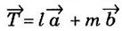 where l and m are integers,
  are the translation vectors in X and Y directions.
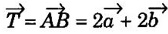 as shown in fig 1.3(a)
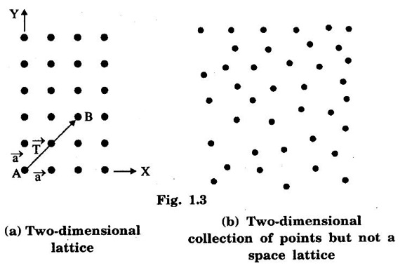
 such that
  are the translation vectors.
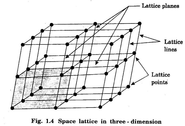
Basis
 corresponding to AB and AD, the whole pattern (or array) is obtained.
 are basis vectors.
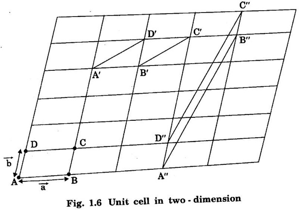

Lattice parameters of the unit cell
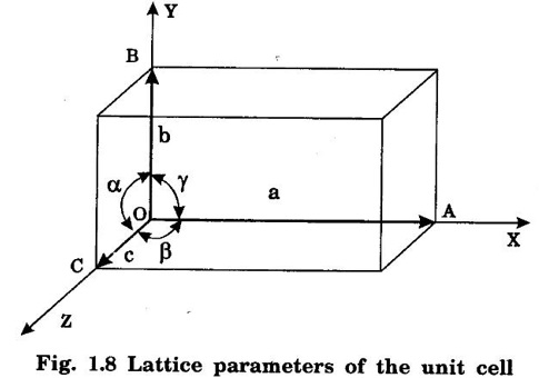
Interfacial angles
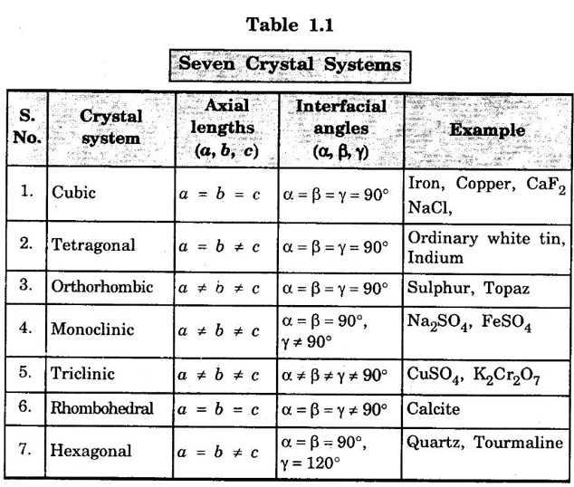
Crystal Systems
1. Cubic system
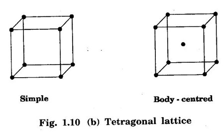
2. Tetragonal system

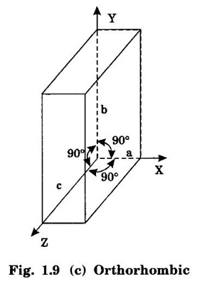
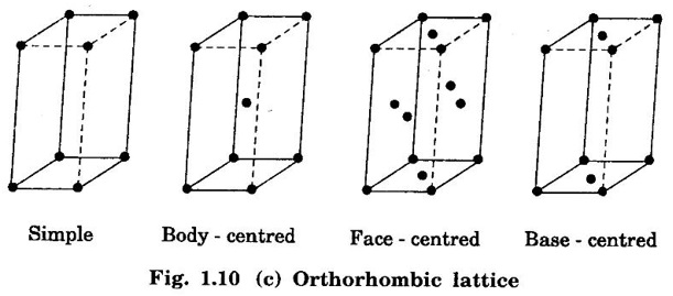
3. Orthorhombic system
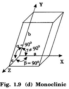
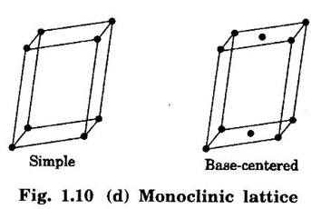
4. Monoclinic system
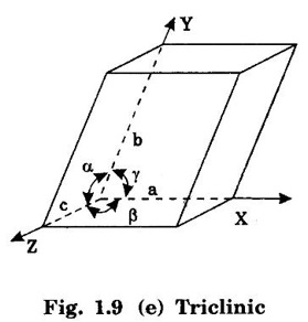
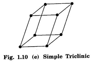
5. Triclinic system
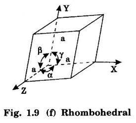
6. Rhombohedral system (Trigonal)
7. Hexagonal system
Bravais Lattice
Primitive cell
Non - primitive cell
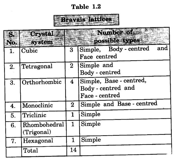
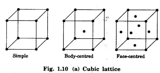
1. Cubic lattice
2. Tetragonal lattice
3. Orthorhombic lattice
4. Monoclinic lattice
5. Triclinic lattice
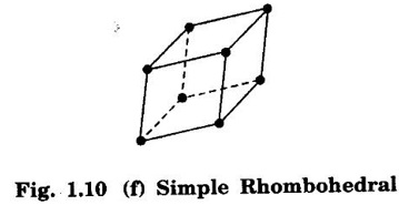
6. Rhombohedral lattice
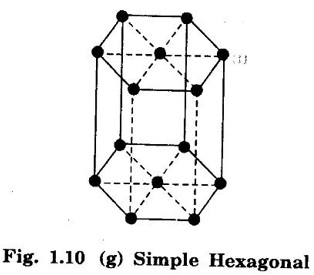
7. Hexagonal lattice
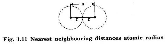
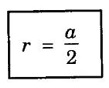
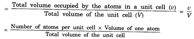
Characteristics of the unit cell
Materials Science: Unit I: Crystallography : Tag: : Definition, Crystal Systems, Crystal Structure, Characteristics - Crystallography
Related Topics
Related Subjects

Materials Science
PH3251 2nd semester Mechanical Dept | 2021 Regulation | 2nd Semester Mechanical Dept 2021 Regulation