Basic Electrical and Electronics Engineering: Unit III: Analog Electronics
Silicon Controlled Rectifier (SCR)
Construction, Operation Working Principle, Important Features, Basic Structure, Classification, Symbol, Biasing, VI Characteristics, Drawbacks, Advantages, Applications
SCR is one of the oldest type of solid state power device. It was invented in 1957 by the Generate Electric Research Laboratories.
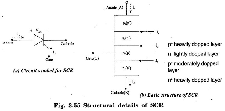
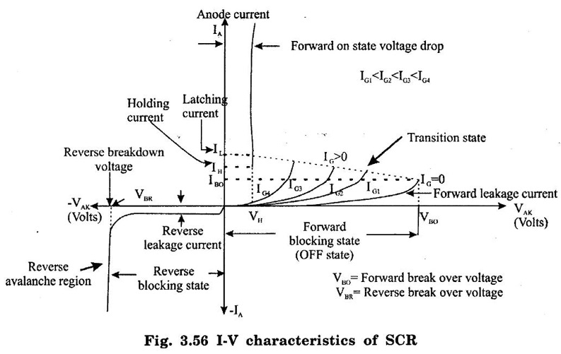
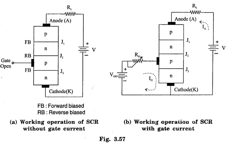
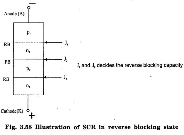
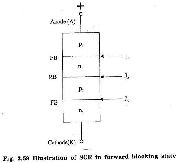
SILICON CONTROLLED RECTIFIER (SCR) SCR is one of the oldest type of solid state power device. It was invented in 1957 by the Generate Electric Research Laboratories. SCRs have the highest power handling capacity of all the power semiconductor devices. They have a four layer construction with three user accessible terminals SCR is a latching type device that can be turned on by the control terminal (gate) but once turned on the gate loses control on it (i.e. it cannot be turned by the gate) Important Features of SCR (i) It is a latching type device. (ii) It can handle a very laerge power. (iii) It is a current controlled device, because the gate current controls SCR. (iv) It acts as an open or closed switch. (v) It can handle thousands of amperes of current. The basic structure of SCR has been shown in figure 3.55(b). It is a four layer pnpn device, with three terminals brought out for the user, namely Anode, Cathode and Gate. The gate terminal is the control terminal that can turn on the device whenever required. The symbol of SCR has been shown in figure 3.55(a). It is essentially the symbol of a rectifying diode with a third control terminal, the gate added to it. The direction of forward anode current, voltage across the thyristor and direction of conventional gate current have been shown in figure.3.55(a) Number of Junctions As observed from figure 3.55(b), there are three junctions J1, J2 and J3. In order to turn on SCR, the anode must be at a higher positive potential than cathode. This means that SCR must be forward biased. Current Directions The directions of the anode and gate current in figure 3.55(a) are conventional directions. It clearly indicates that SCR is a unidirectional device and that the gate current can be only positive. The gate current can flow only in one direction i.e. into the gate terminal. The I-V characteristics of SCR is a graph of anode current IA on y-axis and anode to cathode voltage plotted on the x-axis as shown in figure 3.56. The I-V Characteristics can be split into two parts namely the forward characteristics and reverse characteristics. The characteristics in the reverse direction (anode to cathode voltage negative) is similar to a reverse biased diode. For small reverse voltage, a small reverse leakage current flows until the avalanche breakdown takes place at reverse break over voltage VBR. As soon as the reverse breakdown takes place due to avalanche breakdown, a large current flows through SCR whereas the voltage across the device remains constant. It is dangerous to operate SCR in the reverse breakdown state because it may get damaged due to overheating. The region from 0 volts upto VBR Volts in which the SCR is reverse biased and non-conducting is called as reverse blocking state. 1. Forward characteristics under: The forward characteristics may be divided into three regions of operation as (i) Forward blocking state (ii) Transition state (iii) The Low Voltage High Current Mode or the ON state (i) Forward blocking state : This is the high voltage low current mode of operation in which SCR is in the OFF state. The current through it is Forward Leakage Current. This current flows due to thermally generated minority carriers. (ii) Transition state: SCR remains in the blocking state as long as the forward anode to cathode voltagage is less than the break over voltage. As soon as VAK becomes greater than the break over value, the anode current IA increases sharply to a high value and the voltage across SCR reduces sharply to a low value (on state voltage). The switching of SCR from off state to on state and viceversa takes place in a short time. This change over state is called as transition state. As this is an unstable state, it is shown by dotted line in figure. (iii) The Low Voltage High Current Mode or the ON state The voltage across SCR is low in this state. In the on state a high power SCR can conduct average currents as large as 2000 amp with on state voltage drop of a few volts. 2. Unstable state These two stable starts or modes are connected together by an unstable mode (called as the transition mode) of proportion that appears as a negative resistance on the I-V characteristics. (dotted line in figure 3.56) The important voltage and current terms in the I-V characteristics may be listed as under : (i) The forward breakover voltage (VBO) This is the maximum forward voltage that can be applied between anode and cathode, without initiating forward conduction. This voltage is defined for a zero gate current. In short, this is the maximum forward voltage across SCR in its off state. (ii) The forward leakage current This is the small current flowing in the forward direction in the off state of the device. This current is generated due to the minority current carriers and therefore is dependent on the operating temperature. (iii) The holding current (IH) It represents the minimum current that can flow through SCR and still hold it in the on state. The accompanying voltage is termed as holding voltage VH. If the forward anode current is reduced below holding current, SCR will be turned off. The holding current is defined for zero gate current (IG = 0) (iv) ON state voltage It may be noted that the voltage across SCR in its on state is very low as compared to the off state voltage. It will be proved later on that the on state voltage is equal to drop across one junction (i.e. the order of 1 to 1.5 volts) (v) Latching current (IL) It is minimum anode current that must flow through SCR to latch it into the on state. The latching current is higher than the holding current. The latching current is important when SCR is being turned on. Working operation of SCR can be explained under two different operating conditions. These two operating conditions are as under : 1. Working Operation Without Gate Current Let us consider figure 3.57(a). The gate terminal of SCR is left open so that IG = 0. SCR is forward, biased by applying a positive voltage to anode with respect to cathode. Out of the three junctions, the junctions J1 and J3 are forward biased and junction J2 is reverse biased. Therefore, current does not flow through the SCR. As the anode to cathode voltage is increased, the voltage across junction J2 increases. At a certain voltage, this junction will breakdown and SCR will start conducting. This voltage is called as forward breakover voltage. Operation With Gate Current Let us consider figure 3.57(b). It illustrates that SCR is forward biased as before and the gate cathode junction also is forward biased using an external power source. The gate current IG states flowing which can be adjusted by the resistance RG. As explained earlier, the value of gate current decides breakover voltage of SCR. As IG increases, breakover voltage will decrease i.e., SCR will turn on at lower voltage. Reverse Blocking Capacity In the reverse blocking state, anode is biased negative with respect to cathode. Therefore, the junctions J1 and J3 in figure 3.58(a) are reverse biased and junction J2 is forward biased. Out of the two reverse biased junction J1 and J3, the lower junction J3 has a low breakdown voltage due to the heavy doping on both sides of it. Hence, the reverse blocking capacity depends entirely on junction J1. Therefore blocking capacity of junction J1 is usually decided by the length of n − (n1) region. Forward Blocking Capacity of SCR In the forward blocking state, the thyristor has to block a forward voltage because anode is biased positive with respect to cathode. Therefore, the junctions J1 and J3 are forward biased, and junction J2 is reverse biased. The junction J2 has to block the entire anode to cathode voltage. In order to achieve this, the n - 1 layer (n1) in figure 3.58(b) is lightly doped and made wide enough. The depletion region of the reverse biased J2 junction appears in this layer (n1 layer). Thus, this region decides the forward blocking voltage. Drawbacks of SCR (i) It can conduct only in one direction. Hence, it can control power only during one half cycle of ac. (ii) It can turn on accidently due to high dv/dt of the source voltage. (iii) It is not easy to turn off the conducting SCR. We have to use special circuits called commutation circuits to turn off SCR. (iv) SCR can not be used at high frequencies. The maximum frequency of its operation is 400 Hz. (v) Gate current can not be negative. Advantages of SCR (i) It can handle large voltages, currents and power. (ii) The voltage drop across conducting SCR is small. This will reduce the power dissipation in the SCR. (iii) Easy to turn on. (iv) Triggering circuits are simple. (v) It can be protected with the help of a fuse. (vi) We can control the power delivered to the load. Applications of SCR (i) Controlled rectifiers. (ii) DC to AC converters or choppers (iii) DC to AC converters or inverters (iv) As static switch (v) Battery charger (vi) Speed control of DC and AC motors (vii) Lamp dimmers (viii) AC voltage stabilizers.1. Basic Structure of SCR
2. I-V Characteristics
3. Working Operation of SCR
Basic Electrical and Electronics Engineering: Unit III: Analog Electronics : Tag: : Construction, Operation Working Principle, Important Features, Basic Structure, Classification, Symbol, Biasing, VI Characteristics, Drawbacks, Advantages, Applications - Silicon Controlled Rectifier (SCR)
Related Topics
Related Subjects

Basic Electrical and Electronics Engineering
BE3251 2nd semester Mechanical Dept | 2021 Regulation | 2nd Semester Mechanical Dept 2021 Regulation

Basic Electrical and Electronics Engineering
BE3251 2nd Semester CSE Dept 2021 | Regulation | 2nd Semester CSE Dept 2021 Regulation