Basic Electrical and Electronics Engineering: Unit III: Analog Electronics
Inverters
Operation Working Principle, Circuit Diagram, Waveform
An inverter is a device that change dc power into ac power (just the opposite of converters).
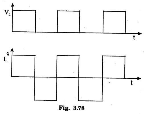
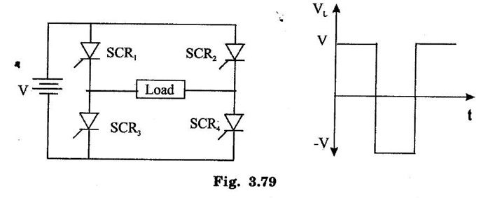
INVERTERS An inverter is a device that change dc power into ac power (just the opposite of converters). The inversion process can be achieved with the help of transistors, SCRs and tunnel diodes etc. For low and medium outputs, transistorized inverters are suitable but for high power outputs. SCR inverters are essential. For very low voltage and high current requirements, tunnet diode invertors are used. For inverter applications, transistors have definite advantages over SCRS regarding the switching speed, simplicity of control circuitry, high efficiency and greater reliability. It is mainly due to this fact that SCR inverters require complicated circuitry for triggering and commutation. The basic working principle of an inverter may be explained with the help of circuit shown in fig. 3.77. It is called voltage-driven inverter because a dc voltage source is connected through semiconductor switches directly to the primary of a transformer. In fig. 3.77 S1 and S2 are switching devices (transistors or SCRs) which open and close alternately at regular intervals of time. The two switching devices are generally driven by an astable multi-vibrator operating at the desired frequency. When S1 is closed, the entire dc source voltage V is applied across points A and B of the transformer primary. S1 remains closed for a certain period of time after which it is cut off and S1 closes. It also remains closed for the same period of time during which the source voltage V is impressed across points B and C of the primary. S2 then opens out and S1 closes. In this way, an alternating voltage is applied across the primary which induces an ac voltage in the secondary. Since de supply voltage is connected directly across the primary, the output waveform of the secondary voltage is a square wave Fig. 3.78 irrespective of the type of load and load power factor. However, the waveforms of both the primary and secondary currents depend on the type of load whether resistive, inductive or capacitive. Fig. 3.79 shows a single-phase inverter with a load resistor using 4 SCRS working in pairs. The triggering and commutating circuitry of the SCRS has not been shown in the figure. The two thyristors SCR1 and SCR4 are triggered simultaneously so that load current passes through RL from left to right. Exactly when these two SCRs are switched off by commutating circuitry, thyristors SCR2 and SCR3 are RL from right to left. Hence, an ac voltage is developed across the load whose waveform is as shown in fig. 3.79 Fig. 3.80 shows an inverter which employees two SCRS and one transformer. These two SCRs are triggered into conduction alternately for the same period of time. As a result, current through the primary becomes alternating which induces an ac voltages across the secondary and hence the load. The secondary ac voltage has a square waveform. The capacitor C is connected across the anodes of the two SCRS and provides commutation i.e., switching off of the SCRS. The capacitor charges to double the supply voltage as a result of transformer action between the two halves of the primary winding. This large voltage is sufficient to reverse-bias the SCRs and drive the holding current below its rated value.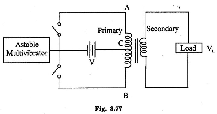
1. Single-phase Inverter
2. Push-Pull Inverter

Basic Electrical and Electronics Engineering: Unit III: Analog Electronics : Tag: : Operation Working Principle, Circuit Diagram, Waveform - Inverters
Basic Electrical and Electronics Engineering: Unit III: Analog Electronics
Under Subject

Basic Electrical and Electronics Engineering
BE3251 2nd semester Mechanical Dept | 2021 Regulation | 2nd Semester Mechanical Dept 2021 Regulation

Basic Electrical and Electronics Engineering
BE3251 2nd Semester CSE Dept 2021 | Regulation | 2nd Semester CSE Dept 2021 Regulation
Related Subjects

Professional English II
HS3251 2nd Semester 2021 Regulation | 2nd Semester Common to all Dept 2021 Regulation

Statistics and Numerical Methods
MA3251 2nd Semester 2021 Regulation M2 Engineering Mathematics 2 | 2nd Semester Common to all Dept 2021 Regulation

Engineering Graphics
GE3251 eg 2nd semester | 2021 Regulation | 2nd Semester Common to all Dept 2021 Regulation

Physics for Electrical Engineering
PH3202 2nd Semester 2021 Regulation | 2nd Semester EEE Dept 2021 Regulation

Basic Civil and Mechanical Engineering
BE3255 2nd Semester 2021 Regulation | 2nd Semester EEE Dept 2021 Regulation

Electric Circuit Analysis
EE3251 2nd Semester 2021 Regulation | 2nd Semester EEE Dept 2021 Regulation

Physics for Electronics Engineering
PH3254 - Physics II - 2nd Semester - ECE Department - 2021 Regulation | 2nd Semester ECE Dept 2021 Regulation

Electrical and Instrumentation Engineering
BE3254 - 2nd Semester - ECE Dept - 2021 Regulation | 2nd Semester ECE Dept 2021 Regulation

Circuit Analysis
EC3251 - 2nd Semester - ECE Dept - 2021 Regulation | 2nd Semester ECE Dept 2021 Regulation

Materials Science
PH3251 2nd semester Mechanical Dept | 2021 Regulation | 2nd Semester Mechanical Dept 2021 Regulation
Basic Electrical and Electronics Engineering
BE3251 2nd semester Mechanical Dept | 2021 Regulation | 2nd Semester Mechanical Dept 2021 Regulation

Physics for Civil Engineering
PH3201 2021 Regulation | 2nd Semester Civil Dept 2021 Regulation

Basic Electrical, Electronics and Instrumentation Engineering
BE3252 2021 Regulation | 2nd Semester Civil Dept 2021 Regulation

Physics for Information Science
PH3256 2nd Semester CSE Dept | 2021 Regulation | 2nd Semester CSE Dept 2021 Regulation
Basic Electrical and Electronics Engineering
BE3251 2nd Semester CSE Dept 2021 | Regulation | 2nd Semester CSE Dept 2021 Regulation

Programming in C
CS3251 2nd Semester CSE Dept 2021 | Regulation | 2nd Semester CSE Dept 2021 Regulation