Basic Electrical and Electronics Engineering: Unit III: Analog Electronics
Half Wave Rectifier
Construction, Operation Working Principle, Circuit Diagram, Waveform, Formula, Calculation
In half wave rectifier, diode conducts only during positive half cycle of input ac supply. The negative half cycle of ac supply are eliminated from the output.
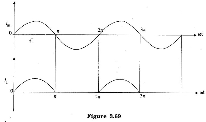
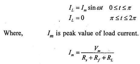
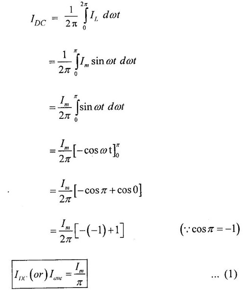
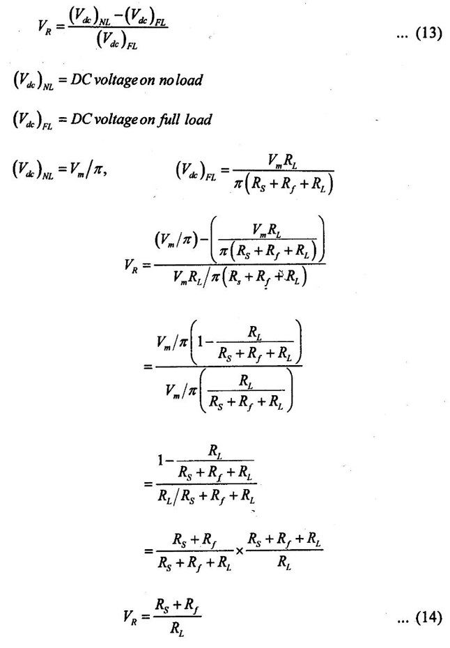
HALF WAVE RECTIFIER In half wave rectifier, diode conducts only during positive half cycle of input ac supply. The negative half cycle of ac supply are eliminated from the output. This rectifier circuit consists of resistive load and transformer for step down the input voltage. During positive half cycle of the ac input supply, diode D conducts. The current IL flows through load resistor RL. During negative half cycle of the ac input supply, diode D reverse biased. It does not conduct. No current flows through load resistor RL. The result is that output voltage consist of positive half cycles of input ac voltage while negative half cycles are suppressed. It may be seen that output across load resistor RL is pulsating d.c. The average (or) dc value of alternating current is obtained by integration. For finding out the average value of an alternating signal we have to determine the area under the curve over one complete cycle.(i.e) from 0 to 2л and then dividing it by the base (i.e) 2. Mathematically current waveform can be expressed as, Where Rs - Winding resistance Rf - Diode resistance RL - Load resistance It is the product of average D.C. load current and the load resistance RL Substitute equation (3) in (2) RMS value of the set of values is square root of the arithmetic mean of the squares of the original values (or square of the function that defines the continuous waveform.) The dc power output can be determined as, The power input taken from the secondary of transformer is the power supplied to three resistances namely load resistance RL the diode resistance Rf and winding resistance RS. The ac power is given as, PAC = I2RMS (RL + Rf + Rs) The rectifier efficiency is defined as the ratio of output dc power to input ac power. Mathematically, ripple factor is defined as the ratio of R.M.S value of the ac component to the dc component in the output. Iac = RMS value of ac component present in output Idc = DC component present in output IRMS = RMS value of total output current The ripple factor for half wave rectifier is very high which indicates that the half wave rectifier circuit is a poor converter of ac to dc. The ripple factor is minimized using filter circuits along with the rectifiers. The TUF is defined as the ratio of dc power delivered to the load to the ac power rating of the transformer. We know that. Substitute (11) in (10), Since from equation (4) 9. Voltage Regulation When we are neglecting 'RS' value voltage regulation = Rf/RL since RS << Rf Less the value of voltage regulation, better is the performance of rectifier circuit. The peak inverse is the voltage across the diode in the reverse direction. When the diode is reverse bias the current across the diode is zero. Hence maximum value of reverse voltage which occurs at the peak of the input cycle when the diode is reverse biased. Peak inverse voltage of half wave rectifier is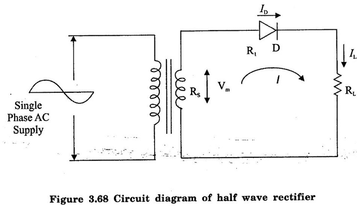
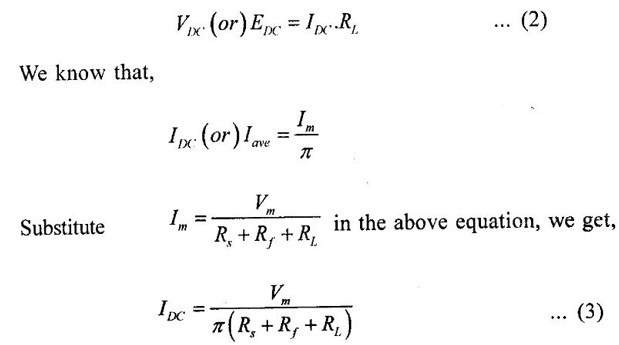
1. Average DC Load Current (I DC)
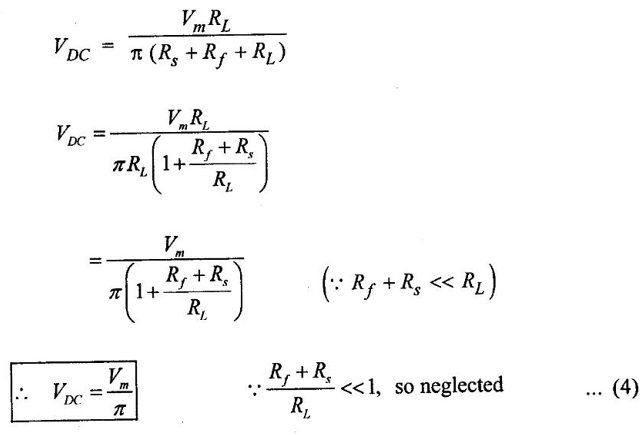
2. Average DC Load Voltage (EDC or VDC)
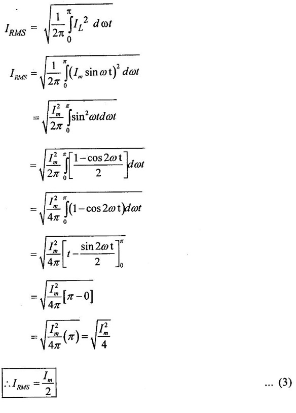
3. Mean Square Value of Load Current (IRMS)
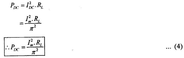
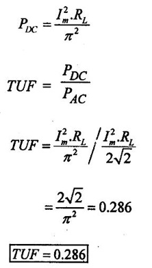
4. DC Power Output (PDC)
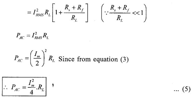
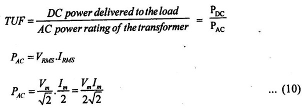
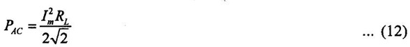
5. AC Power Input (PAC)
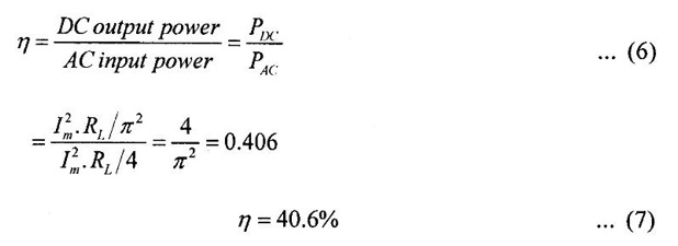
6. Rectifier Efficiency (η)
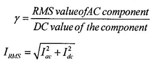
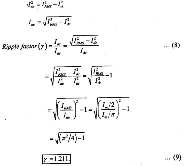
7. Ripple Factor (γ)
8. Transformer Utilization Factor (TUF)

10. Peak Inverse Voltage
Basic Electrical and Electronics Engineering: Unit III: Analog Electronics : Tag: : Construction, Operation Working Principle, Circuit Diagram, Waveform, Formula, Calculation - Half Wave Rectifier
Related Topics
Related Subjects

Basic Electrical and Electronics Engineering
BE3251 2nd semester Mechanical Dept | 2021 Regulation | 2nd Semester Mechanical Dept 2021 Regulation

Basic Electrical and Electronics Engineering
BE3251 2nd Semester CSE Dept 2021 | Regulation | 2nd Semester CSE Dept 2021 Regulation