Engineering Graphics: Unit 0 (c): Lines, Lettering and Dimensioning
General Rules of Dimensioning
Engineering Graphics (EG)
Following are the rules of dimensioning generally followed while dimensioning a drawing.
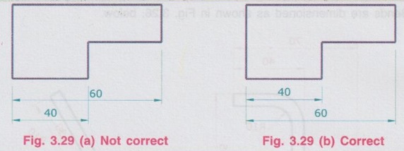
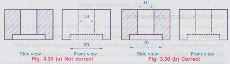
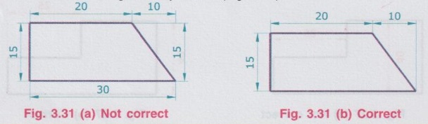
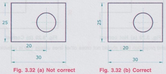
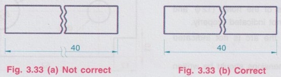
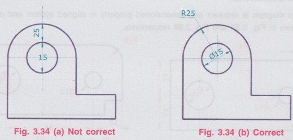
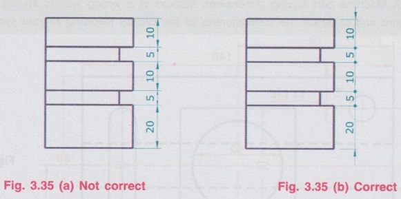
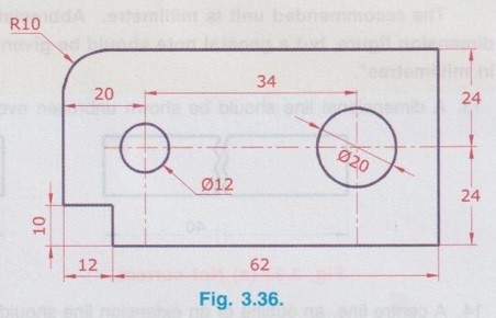
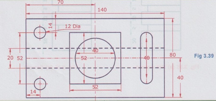
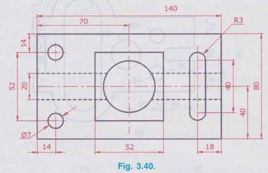
GENERAL RULES OF DIMENSIONING Following are the rules of dimensioning generally followed while dimensioning a drawing. 1. Dimension lines and projection lines are drawn as continuous thin lines. 2. Projection lines should extend slightly beyond the dimension line approximately to 3mm. 3. Numerals and letters should be bold and large enough to ensure easy readings. 4. Dimension values should be placed approximately at the middle unless unavoidable due to lack of space. 5. Dimensions should not be placed within a view. (Fig. 3.27) 6. Dimension lines should be placed at sufficient distance from the parts being dimensioned, preferably at a distance of 6 to 10 mm (Fig. 3.28). 7. Extension and projection lines should not cross other lines unless that is unavoidable.(Fig. 3.29) For this condition, smaller dimensions should be placed near the view and larger dimensions should be placed away from the view. 8. Dimensions are to be given from visible outlines rather than from hidden lines (Fig. 3.30). 9. Each end of dimension line should be defined by an arrow head, proportional to the line thickness and size of the drawing. The ratio of length to width of arrow head should be 3: 1. 10. Each dimension should be given only once. (Fig. 3.31). For this condition, a dimension given in one view (say height in front view) should not be repeated in another view (the same height in side view). 11. Two systems of dimensioning should not be mixed up in one drawing. (Fig. 3.32) For this rule, only one system of dimensioning either aligned (or) unidirectional should be followed throughout in a particular drawing. 12. Dimensions in one particular drawing should be expressed in one unit only. The recommended unit is millimetre. Abbreviated 'mm' should not be written with each dimension figure, but a general note should be given in title block that “All the dimensions are in millimetres”. 13. A dimensional line should be shown unbroken even if the feature is broken (Fig. 3.33) 14. A centre line, an outline or an extension line should not be used as a dimension line. (Fig. 3.34) 15. If the space is limited the arrowheads may be reversed or may be replaced by a clearly marked dot. (Fig. 3.35). Example 1 : Read the dimensioned drawing of a lock plate shown in Fig. 3.36 and redraw the figure to full size and dimension it in (i) Aligned system and (ii) Unidirectional system as per Bureau of Indian standards. Take all the dimensions are in mm. The mistakes to be corrected in the given drawing are : i) The dimensions 20 and 34 are to be placed outside the view. ii) Dimensions of the holes (12ϕ and ϕ 20) are not indicated properly. iii) Radius of the arc is not indicated properly. iv) All the dimensions should be written following any one system, either aligned or unidirectional. The given diagram is redrawn and dimensioned properly in aligned system and unidirectional system as shown in Fig. 3.37 and Fig. 3.38 respectively. Example 2 : A Machine part having dimensions marked in a wrong way is shown in Fig. 3.39. Redraw the figure and complete the dimensioning as per BIS by following aligned system. The given drawing is redrawn and dimensions are marked properly in Aligned system as shown in Fig. 3.40. 1. Read the drawings shown in Fig. 3.41 to Fig. 3.45 and redraw to their full size. Complete the dimensions as per Indian Standards. Take all the dimensions are in millimetres.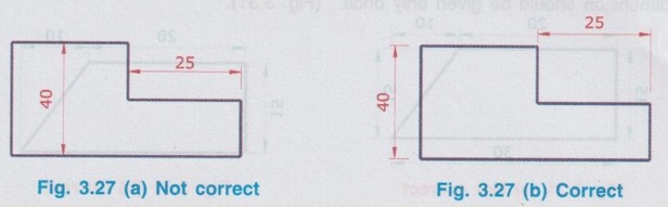


EXERCISE

Engineering Graphics: Unit 0 (c): Lines, Lettering and Dimensioning : Tag: : Engineering Graphics (EG) - General Rules of Dimensioning
Engineering Graphics: Unit 0 (c): Lines, Lettering and Dimensioning
Under Subject

Engineering Graphics
GE3251 eg 2nd semester | 2021 Regulation | 2nd Semester Common to all Dept 2021 Regulation
Related Subjects

Professional English II
HS3251 2nd Semester 2021 Regulation | 2nd Semester Common to all Dept 2021 Regulation

Statistics and Numerical Methods
MA3251 2nd Semester 2021 Regulation M2 Engineering Mathematics 2 | 2nd Semester Common to all Dept 2021 Regulation
Engineering Graphics
GE3251 eg 2nd semester | 2021 Regulation | 2nd Semester Common to all Dept 2021 Regulation

Physics for Electrical Engineering
PH3202 2nd Semester 2021 Regulation | 2nd Semester EEE Dept 2021 Regulation

Basic Civil and Mechanical Engineering
BE3255 2nd Semester 2021 Regulation | 2nd Semester EEE Dept 2021 Regulation

Electric Circuit Analysis
EE3251 2nd Semester 2021 Regulation | 2nd Semester EEE Dept 2021 Regulation

Physics for Electronics Engineering
PH3254 - Physics II - 2nd Semester - ECE Department - 2021 Regulation | 2nd Semester ECE Dept 2021 Regulation

Electrical and Instrumentation Engineering
BE3254 - 2nd Semester - ECE Dept - 2021 Regulation | 2nd Semester ECE Dept 2021 Regulation

Circuit Analysis
EC3251 - 2nd Semester - ECE Dept - 2021 Regulation | 2nd Semester ECE Dept 2021 Regulation

Materials Science
PH3251 2nd semester Mechanical Dept | 2021 Regulation | 2nd Semester Mechanical Dept 2021 Regulation

Basic Electrical and Electronics Engineering
BE3251 2nd semester Mechanical Dept | 2021 Regulation | 2nd Semester Mechanical Dept 2021 Regulation

Physics for Civil Engineering
PH3201 2021 Regulation | 2nd Semester Civil Dept 2021 Regulation

Basic Electrical, Electronics and Instrumentation Engineering
BE3252 2021 Regulation | 2nd Semester Civil Dept 2021 Regulation

Physics for Information Science
PH3256 2nd Semester CSE Dept | 2021 Regulation | 2nd Semester CSE Dept 2021 Regulation

Basic Electrical and Electronics Engineering
BE3251 2nd Semester CSE Dept 2021 | Regulation | 2nd Semester CSE Dept 2021 Regulation

Programming in C
CS3251 2nd Semester CSE Dept 2021 | Regulation | 2nd Semester CSE Dept 2021 Regulation