Engineering Graphics: Unit 0 (c): Lines, Lettering and Dimensioning
Elements of Dimensioning
Engineering Graphics (EG)
Elements of dimensioning are listed as below.
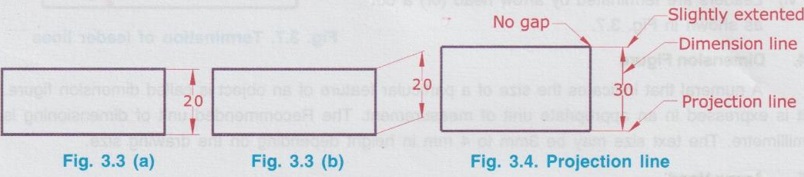
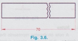
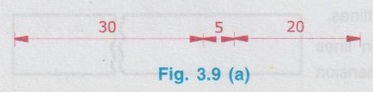
ELEMENTS OF DIMENSIONING Elements of dimensioning are listed as below. 1. Projection line 2. Dimension line 3. Leader line 4. Symbol 5. Dimension Figure 6. Arrow Head 7. Notes These elements of dimensioning are shown in Fig. 3.2. The elements of dimensioning shown in Fig. 3.2. are explained in detail below. Projection lines are used to specify the boundary of a dimension line. It is drawn as a continuous thin line. While drawing the projection line the following points should be observed. i) It is perpendicular to the feature to be dimensioned (Fig. 3.3 a) It can also be drawn obliquely but parallel with each other as shown in Fig. 3.3 b. ii) Projection line to be extended slightly (about 3mm) beyond the respective dimension line (Fig. 3.4) iii) Projection line should not cross other dimension line, unless unavoidable. iv) Centre line and outline can be used as projection lines (Fig. 3.5) Projection line is also called as extension line. Dimension line is used to indicate the measurement. It is drawn as a thin continuous line. The measurement is denoted in figures and placed near the middle of the dimension line. While drawing the dimension line the following points must be observed. i) Dimension line should not cross other lines, unless unavoidable. ii) A centre line or outline of a part should not be used as a dimension line. iii) Dimension line should be drawn from visible outlines. iv) Dimension line should be ended with projection lines parallel to each other but perpendicular to the dimension line. v) A broken feature should be marked by an unbroken dimension line. (Fig. 3.6) Leader line is used as a dimension line in inclined position to write a note or dimensional figure on it. It is drawn as a thin continuous line from note of the figure to show where it applies. While drawing a leader line the following points are observed. i) Leaders should not be inclined less than 30°. ii) Leaders should not be parallel to adjacent dimensions or projection lines. iii) Leaders should not be drawn as vertical, horizontal or curved. iv) One end of the leader line should be terminated on a short horizontal bar below the lettering. v) Use of common leaders to be avoided. vi) Leaders are terminated by arrow head (or) a dot as shown in Fig. 3.7. A numeral that indicates the size of a particular feature of an object is called dimension figure. It is expressed in an appropriate unit of measurement. The Recommended unit of dimensioning is millimetre. The text size may be 3mm to 4 mm in height depending on the drawing size. Arrow heads are used to terminate dimension lines which touch the projection lines and indicate the extent of a dimension. The common types of arrow heads recommended by BIS are shown in Fig. 3.8(a). It is normally used the closed filled arrow heads in engineering drawings with its length about three times the width as shown in Fig. 3.8(b). The size of the arrow heads should be proportionate to the thickness of the lines of the drawing. Normally, length of arrow heads is 3mm for small drawings and 4 to 5 mm for large drawings. where the space is limited, adjacent arrow-heads may be used as shown in Fig. 3.9(a) (or) adjacent arrow-heads may be replaced by dots as shown in Fig. 3.9(b). A note on drawing represents the complete information regarding specific operation relating to a feature. It is generally placed outside a view. A symbol is the representation of any object by some mark on the drawing. A symbol is used to save time and labour of drawing work. For example SR is used for spherical radius R is used for Radius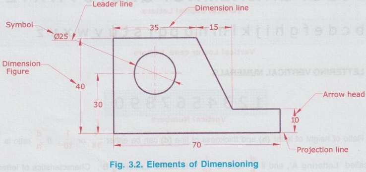
1. Projection line

2. Dimension line
3. Leader line

4. Dimension Figure
5. Arrow Head


6. Notes
7. Symbol
![]() is used to denote diameter
is used to denote diameter![]() is used for spherical diameter
is used for spherical diameter![]() is used to denote square shape
is used to denote square shape
Engineering Graphics: Unit 0 (c): Lines, Lettering and Dimensioning : Tag: : Engineering Graphics (EG) - Elements of Dimensioning
Engineering Graphics: Unit 0 (c): Lines, Lettering and Dimensioning
Under Subject

Engineering Graphics
GE3251 eg 2nd semester | 2021 Regulation | 2nd Semester Common to all Dept 2021 Regulation
Related Subjects

Professional English II
HS3251 2nd Semester 2021 Regulation | 2nd Semester Common to all Dept 2021 Regulation

Statistics and Numerical Methods
MA3251 2nd Semester 2021 Regulation M2 Engineering Mathematics 2 | 2nd Semester Common to all Dept 2021 Regulation
Engineering Graphics
GE3251 eg 2nd semester | 2021 Regulation | 2nd Semester Common to all Dept 2021 Regulation

Physics for Electrical Engineering
PH3202 2nd Semester 2021 Regulation | 2nd Semester EEE Dept 2021 Regulation

Basic Civil and Mechanical Engineering
BE3255 2nd Semester 2021 Regulation | 2nd Semester EEE Dept 2021 Regulation

Electric Circuit Analysis
EE3251 2nd Semester 2021 Regulation | 2nd Semester EEE Dept 2021 Regulation

Physics for Electronics Engineering
PH3254 - Physics II - 2nd Semester - ECE Department - 2021 Regulation | 2nd Semester ECE Dept 2021 Regulation

Electrical and Instrumentation Engineering
BE3254 - 2nd Semester - ECE Dept - 2021 Regulation | 2nd Semester ECE Dept 2021 Regulation

Circuit Analysis
EC3251 - 2nd Semester - ECE Dept - 2021 Regulation | 2nd Semester ECE Dept 2021 Regulation

Materials Science
PH3251 2nd semester Mechanical Dept | 2021 Regulation | 2nd Semester Mechanical Dept 2021 Regulation

Basic Electrical and Electronics Engineering
BE3251 2nd semester Mechanical Dept | 2021 Regulation | 2nd Semester Mechanical Dept 2021 Regulation

Physics for Civil Engineering
PH3201 2021 Regulation | 2nd Semester Civil Dept 2021 Regulation

Basic Electrical, Electronics and Instrumentation Engineering
BE3252 2021 Regulation | 2nd Semester Civil Dept 2021 Regulation

Physics for Information Science
PH3256 2nd Semester CSE Dept | 2021 Regulation | 2nd Semester CSE Dept 2021 Regulation

Basic Electrical and Electronics Engineering
BE3251 2nd Semester CSE Dept 2021 | Regulation | 2nd Semester CSE Dept 2021 Regulation

Programming in C
CS3251 2nd Semester CSE Dept 2021 | Regulation | 2nd Semester CSE Dept 2021 Regulation