Basic Electrical and Electronics Engineering: Unit III: Analog Electronics
Bridge Rectifier
Construction, Operation Working Principle, Circuit Diagram, Waveform, Formula, Calculation
The bridge rectifier circuits are mainly used as, • A power rectifier circuit for converting ac power to dc power.
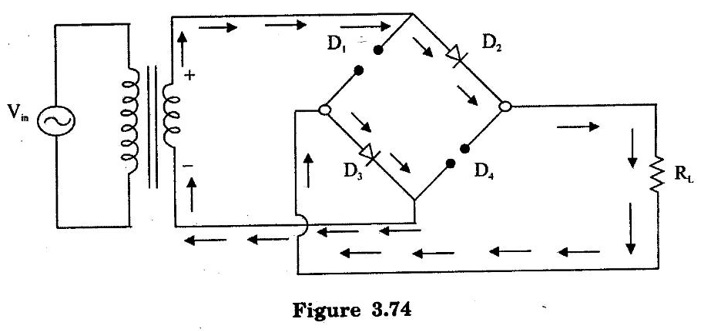
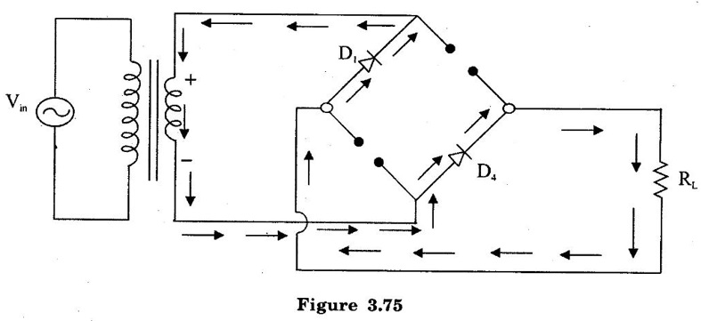
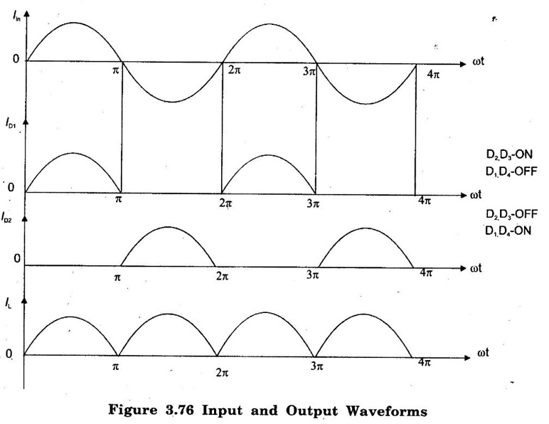
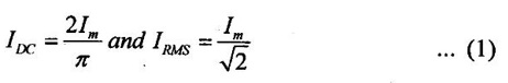
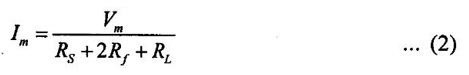
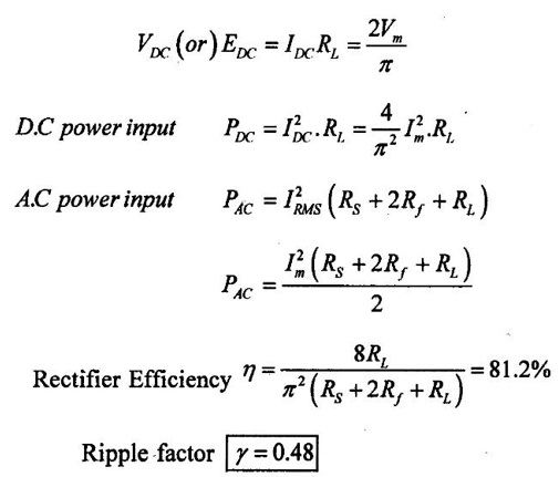
BRIDGE RECTIFIER The bridge rectifier circuits are mainly used as, • A power rectifier circuit for converting ac power to dc power. • A rectifying system in rectifier type ac meters, such as ac voltmeter in which the ac voltage under measurement is first converted into dc and measured with conventional meter. • In this system, the rectifying elements are either copper oxide or selenium type. During positive half cycle of ac input, the diodes D1 and D4 will be reverse biased, while D2 and D3 forward biased. The two diodes D2 and D3 conduct and the current flows through RL as shown in Figure 3.74. During negative half cycle of ac input, the diodes D2 and D3 will be reverse biased, while D1 and D4 forward biased. The two diodes D1 and D4 conduct and the current flows through RL as shown in Figure 3.75. It is seen that in both cycles of ac, the load current is flowing in the same direction. Hence, we get a full wave rectified output. The waveforms of load current and voltage remain exactly. The bridge rectifier circuit, being basically a full wave rectifier circuit characteristics of bridge rectifier is as same as FWR. The relation between the maximum value of load current (Im) and IDC. IRMS remains same as derived earlier for the full wave rectifier circuit. In each half cycle two diodes conduct simultaneously. Hence maximum value of load current is, So the only modification is that instead of Rf which is forward resistance of each diode, the term 2Rf appears in the denominator. The remaining expressions are identical to those derived for two diode full wave rectifier and reproduced for the convenience of the reader. The transformer utilization factor is, TUF = 0.812 The reverse voltage appearing across the reverse biased diodes is 2Vm but two diodes are sharing it. Hence PIV rating of the diode is Vm and not 2Vm as in case of full wave rectifier.
Positive half cycle current flow:
Negative half cycle current flow:
Expressions For Various Parameters
Basic Electrical and Electronics Engineering: Unit III: Analog Electronics : Tag: : Construction, Operation Working Principle, Circuit Diagram, Waveform, Formula, Calculation - Bridge Rectifier
Related Topics
Related Subjects

Basic Electrical and Electronics Engineering
BE3251 2nd semester Mechanical Dept | 2021 Regulation | 2nd Semester Mechanical Dept 2021 Regulation

Basic Electrical and Electronics Engineering
BE3251 2nd Semester CSE Dept 2021 | Regulation | 2nd Semester CSE Dept 2021 Regulation