Engineering Graphics: Unit II (a): Orthographic Projection
Types of Orthographic Projections
Engineering Graphics (EG)
Orthographic projections are classified into two groups such as (i) First angle projection and (ii) Third angle projection, according to the position of the object and the position of planes.
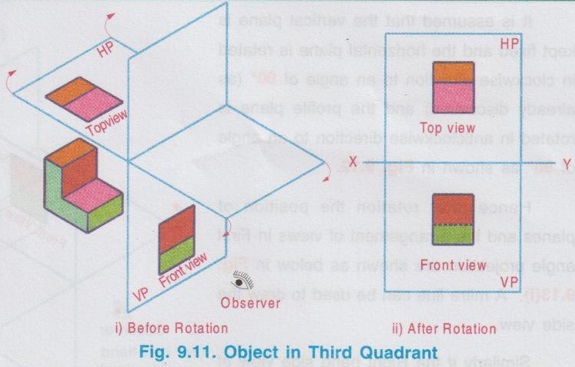
TYPES OF ORTHOGRAPHIC PROJECTIONS Orthographic projections are classified into two groups such as (i) First angle projection and (ii) Third angle projection, according to the position of the object and the position of planes. Two major planes are used to draw the front view and top view. These planes are of infinite thickness and transparent. These two planes are arranged in such a way that they intersect each other at an angle of 90° as shown in Fig. 9.7. The planes shown in Fig. 9.7 form Four quadrants (or) Dihedral angles. Four quadrants are referred as I, II, III and IV Quadrants numbered in anticlockwise direction. The line of intersection of two planes is referred as 'Reference line' denoted by the symbol `XY'. The object may be placed in any one of the four quadrants, but the observer will always be on the right side of the four Quadrants and infront of VP as shown in Fig. 9.7, irrespective of the position of the object in any one of the four quadrants. With this position, the front view is drawn on Vertical plane and the top view is drawn on Horizontal plane (Remember that the planes are transparent; hence when the object is kept back side of the plane also it can be viewed by the observer who is on the front side of plane). In Dihedral angles, shown in Fig. 9.7. It is assumed that the vertical plane is fixed and the horizontal plane is rotated in clockwise direction at an angle of 90°. Hence after rotation, the horizontal plane gets coincide with the vertical plane as shown in Fig. 9.9. If the object is placed in Il quadrant, after obtaining the front view on vertical plane and top view on horizontal plane, and if the planes are rotated to 90°, both Front view (FV) and Top view (TV) will be superimposed and on the same plane above XY reference axis, which leads misrepresentation and confusion. Similarly if the object is placed in IV quadrant and if the planes are rotated to 90° after obtaining the views on the concerned plane, both Front view (FV) and Top view (TV) will be superimposed and observed on the same plane below the reference axis XY. This position of the object is also not suggested to draw the orthographic projections. Where as, if the object is placed in First Quadrant as shown in Fig. 9.10(i), after rotation, front view on vertical plane and top view on horizontal plane can be shown as in Fig. 9.10(ii). Now, both front view and top view can be conveniently drawn with respect to the reference axis XY. Similarly when the object is placed in third Quadrant as shown in Fig. 9.11(i), after rotation, the front view and top view can be drawn with respect to the reference axis as shown in Fig. 9.11(ii). Therefore, to represent the object in various views, the object has to be kept either in First Quadrant (or) in Third Quadrant. It can be seen that the projections (Front view and Top view) are exactly the same for the position of object either in First Quadrant (or) in Third Quadrant, but they are interchanged in arrangement of views. For the object placed in First Quadrant, Front view is drawn above the reference axis and top view is drawn below the reference axis. Whereas, for the object placed in Third Quadrant, Front view is drawn below the reference axis and top view is drawn above the reference axis. The projections so obtained for the object placed in first quadrant is known as 'First angle Projection', and the projections so obtained for the object placed in third quadrant is known as `Third Angle Projection'. Bureau of Indian Standards (B.I.S) [IS 15021 (Parts 1-4) - 2001 ] recommends only First Angle Projection method for the preparation of Engineering Drawings. USSR and other East European countries also follow First angle projection method while US follows third angle projection method. But in UK, both the methods are in common use. All the drawings in this book are presented in First Angle projection method. Students should be able to draw the views in both the methods for better understanding but concentrate more on First angle projection method. Examination point of view, unless (or) otherwise mentioned, draw the views in First angle projection method only. The position of planes and the arrangement of Front view and Top view in First angle projection are explained in the previous article. To draw the side view, a third vertical plane, known as Profile Plane (PP), which is perpendicular to both HP and VP is added as shown in Fig. 9.12. In the figure 9.12, the profile plane is fixed on the right hand side of the object to draw its left side view (Because for First angle projection, object is to be placed in between observer and the plane). Similarly if the right side view of the object is required the profile plane may be fixed on the left hand side of the object. It is assumed that the vertical plane is kept fixed and the horizontal plane is rotated in clockwise direction to an angle of 90° (as already discussed) and the profile plane is rotated in anticlockwise direction to an angle of 90° as shown in Fig. 9.12. Hence after rotation the position of planes and the arrangement of views in First angle projection are shown as below in Fig. 9.13(i). A mitre line can be used to draw the side view. Similarly if the Right hand side view of an object is observed for First angle projection, the views are arranged as shown in Fig. 9.13 (ii). (The arrangement of Front view and Top view are the same; but the Right side view is drawn on the left side of the Front view. This can be verified by keeping the profile plane on the left side of the object and rotating it in clockwise direction to an angle of 90°).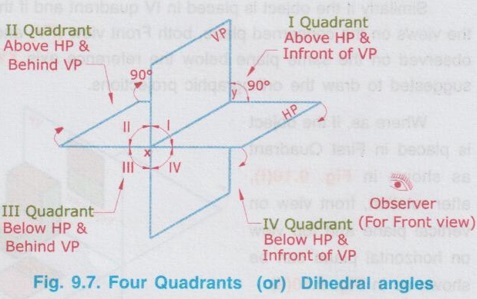


1. SIDE VIEW IN FIRST ANGLE PROJECTION


Engineering Graphics: Unit II (a): Orthographic Projection : Tag: : Engineering Graphics (EG) - Types of Orthographic Projections
Related Topics
Related Subjects

Engineering Graphics
GE3251 eg 2nd semester | 2021 Regulation | 2nd Semester Common to all Dept 2021 Regulation