Basic Electrical and Electronics Engineering: Unit II: Electrical Machines
Transformers
Definition, Classification, Construction, Types, Solved Example Problems
Transformer is a static device, which transforms the electrical power from one circuit to another circuit at the same frequency.
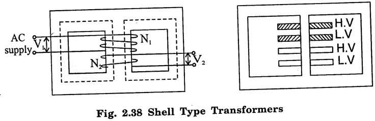
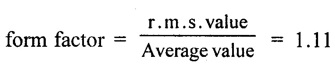
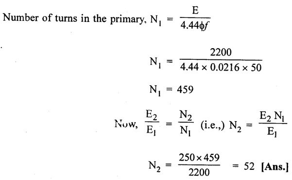
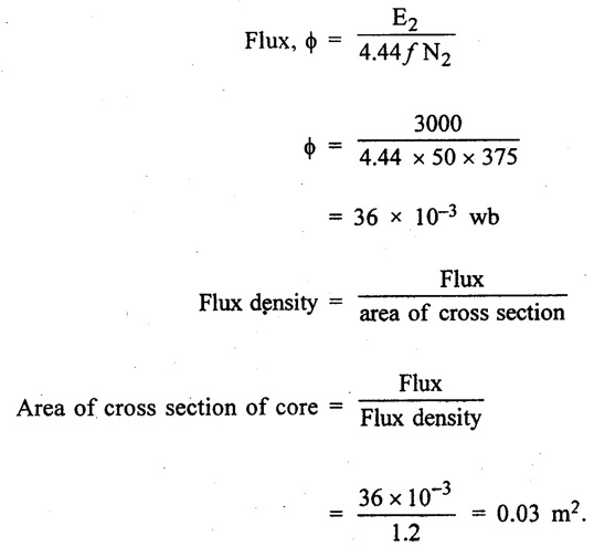
TRANSFORMERS Transformer is a static device, which transforms the electrical power from one circuit to another circuit at the same frequency. It operates on the principle of mutual induction. Transformer is classified on the basis of (i) Construction 1. Core type Transformer 2. Shell type Transformer 3. Berry type Transformer (ii) Voltage output (i) Step down Transformer (ii) Step up Transformer (iii) Auto Transformer (iii) Duty they perform (i) Current Transformer (ii) Potential Transformer (iii) Power Transformer (iv) Application (i) Welding Transformer (ii) Furnace Transformer (iii) Ratio Transformer (v) Input supply (i) Single phase Transformer (ii) Three phase Transformer (vi) Cooling (i) Dry type Transformer (Air natural or Air blast) (ii) Oil immersed Transformer 1. Primary Winding The winding which is connected to ac supply is called primary winding. 2. Secondary winding The winding which is connected to load is called secondary winding. 3. Transformer Core ● The two windings of the transformer is magnetically coupled through the core. ● The magnetic core is a stack of thin silicon laminations to provide continuous magnetic path with a minimum of air gap included. ● The core is made up of silicon steel to reduce the hysteresis loss. ● The laminations reduce the eddy current loss. ● The laminations are insulated from each other by light coat of core plate varnish (or) by an oxide layer on the surface. ● The thickness of the lamination varies from 0.35 mm for a frequency 50 Hz to 0.5 mm for a frequency of 25 Hz. ● The two basic types of transformer construction are: 1. core type, 2. shell type. Another recent development is spiral-core or wound wire type. 1. Core type Transformer Here the windings surround the considerable port of the steel core as shown in figure 2.36. In this type of transformer core will be rectangular in shape and coils are cylindrical. ● There are two limbs in a core type transformer. The two windings are placed in each limb. The windings are made up of two L-type stampings. ● The core type transformer has only one path for the magnetic flux. The effective core area of the transformer can be reduced with the use of laminations and insulations. ● In order to minimize the airgap in the joints between the strips the layers are stacked alternately. 2. Shell Type Transformers ● In shell transformer, the steel core surrounds a major part of the windings. ● There are three limbs in the shell type transformer. The primary and secondary windings are placed in the central limb. i.e., The low voltage and high voltage windings are wound over the central limb and are interleaved (or) sandwiched. ● The windings occupy the entire space in both windows of the core. ● The entire flux passes through the central limb, but divides the outside limb. The core is made up of E and I stampings. ● After the coils are put in place, the core is butted together and held in place by two clamps one at top and other at bottom. The shell type transformer requires more conductor material as compared to core type transformer. ● A transformer operates on the principle of mutual induction between two inductively coupled coils. ● It consists of two windings. The two windings are coupled by magnetic induction. ● Primary winding is energised by a sinusoidal voltage. The secondary winding feeds the load. ● The alternating current in the primary winding set up an alternating flux (6) in the core. ● The secondary windings is linked by most of this flux and emf are induced in the two windings. ● The emf induced in the secondary winding drives current through the load connected to the winding. ● Energy is transfered from the primary circuit to the secondary circuit through the medium of the magnetic field. An ideal transformer is one which has following properties. (i) No winding resistance (ii) No magnetic leakage flux (iii) No core loss (iv) No I2R (i.e.,) copper loss ● Consider an ideal transformer whose primary is connected to sinusoidal alternating voltage V1 and secondary is open as shown in figure 2.39. ● A current flows through the primary winding is called magnetising current (IM) The primary winding draws a small magnetising current IM which lags behind the voltage V1 by 90°. ● This alternating current IM produces an alternating flux ϕ which is inphase with IM. ● This alternating flux ϕ links both the winding and induces emf E1 in the primary and emf E2 in the secondary. Flux ϕ has been taken as the reference phasor, the primary emf E1 and secondary emf E2 lag behind the flux ϕ by 90°. ● Note that E1 and E2 are in phase, but E1 is equal and opposite to V1. Where, N1 = Number of turns in primary winding N2 = Number of turns in secondary winding ϕm = Maximum flux in the core in wb = Bm × A [where Bm is the maximum flux density in the core and A is the core area] f = frequency of ac input in Hz. From figure 2.41, it is clear that since flux increases from its zero value to maximum value ϕm in quarter of the cycle (i.e.,) in 1/4ƒ second. According to Faraday's law of electromagnetic induction, (Consider single turn coil) ⸫ Average value of emf/turn = 4f ϕm V for sinusoidal waveform r.m.s. value = Form factor × Average value r.m.s. value of emf/turn = 1.11 × 4ƒ ϕm = 4.44 f ϕm Volts Therefore, r.m.s. value of emf induced in primary winding E1 = 4.44 f ϕm N1 Volts E1 = 4.4 f Bm AN1 Volts Similarly, r.m.s. value of emf induced in secondary winding E2 = 4.44 ϕ fm N2 Volts E2 = 4.44 ϕ Bm A N2 Volts The transformation ratio is defined as the ratio of the secondary voltage to primary voltage. It is denoted by K. ● If N2 > N1 (i..e,) K > 1 then transformer is called step-up transformer. ● If N2 < N1 (i.e.,) K < 1, then transformer is called step-down transformer. Voltage Transformer Ratio for an Ideal Transformer Input (VA) = output (VA) In a transformer, there are no moving (or) rotating parts. Hence, there is no friction and windage losses. The losses occur in transformer are (i) Core or Iron loss, (ii) Copper loss. (i) Core or Iron loss It includes both hysteresis loss and Eddy current loss. ● Because of core flux remains constant for all loads, the core losses also remain constant. Hysteresis loss, Wh = η Bmax 1.6 ƒV watts. Eddy current loss, We = PB2maxƒ2t2 watts. ● The hysteresis loss is minimized by using steel of high silicon content for the core and eddy current loss is minimized by using thin lamination of the core. (ii) Copper loss This loss is due to the ohmic resistance of the transformer windings. The total copper loss =112R1 + I22R2 = 112R01 = I22R02 where I1 and I2 are primary and secondary circuits R1 and R2 are primary and secondary winding resistances. Efficiency of a Transformer The commercial efficiency of transformer is defined as ratio of output power to input power. i.e., Condition for maximum η: Copper loss = Iron loss All day efficiency All-day efficiency is defined as the ratio of the output energy to the input energy, over 24 hour period. This efficiency is always less than the commercial efficiency of the transformer. Problem 2.22 A 2000/200 V, 20 kVA transformer has 66 turns in the secondary. Calculate (i) primary turns (ii) primary and secondary full-load currents. Neglect the losses. Solution : Fig. 2.42 represents the conditions of the problem. Problem 2.23 A single phase 50 Hz transformer is required to step down from 2200 V to 250 V, the cross sectional area of the core is 36 cm2 and the maximum value of flux density is 6 Wb/cm2. Determine the number of turns in the primary and secondary windings. Solution : Cross sectional area of core, a = 36 × 10-4 m2 Flux density in the core, B = 6 wb/m2 Flux in the core, ϕ = B × a = 6 × 36 × 10-4 = 0.021 Wb Emf induced inthe primary E1 = 4.44 ϕ fN1 volts Problem 2.24 The maximum flux density in the core of a 250/3000 V, 50 Hz single phase transformer is 1.2 wb/m2, if the EMF per turn is 8 volts, determine the primary and secondary turns and the area of the core. Solution : Emf induced per turn = 8 V Number of turns in the primary = 250/8 = 31 Number of turns in the secondary = 3000/8 = 375 Emf induced in the secondary E2 = 4.44 ϕ f N2.Definition
Classification of Transformer
1. Transformer Construction
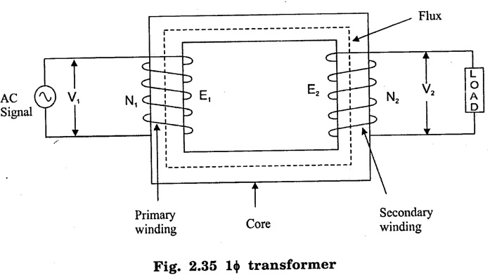 The construction of single phase transformer is shown in fig. 2.35. All transformer has the following essential elements.
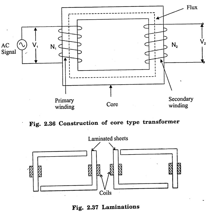
2. Working Principle
3. Ideal Transformer


4. Emf equation of a Transformer


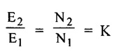
Voltage Transformation Ratio

5. Losses in a Transformer


Basic Electrical and Electronics Engineering: Unit II: Electrical Machines : Tag: : Definition, Classification, Construction, Types, Solved Example Problems - Transformers
Related Topics
Related Subjects

Basic Electrical and Electronics Engineering
BE3251 2nd semester Mechanical Dept | 2021 Regulation | 2nd Semester Mechanical Dept 2021 Regulation

Basic Electrical and Electronics Engineering
BE3251 2nd Semester CSE Dept 2021 | Regulation | 2nd Semester CSE Dept 2021 Regulation