Basic Electrical and Electronics Engineering: Unit II: Electrical Machines
Three Phase Induction Motor
Construction, Operation Working Principle, Starting Method
When a three phase balanced voltage is applied to a three phase balanced winding a rotating magnetic field is produced.
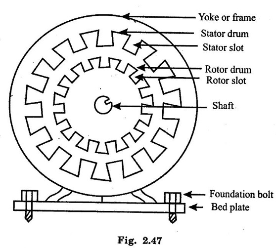
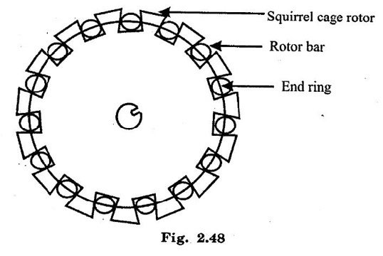
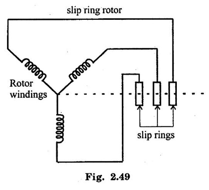
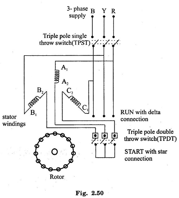
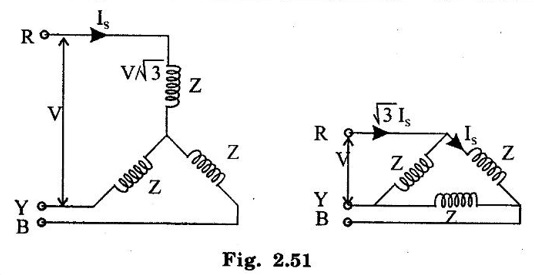
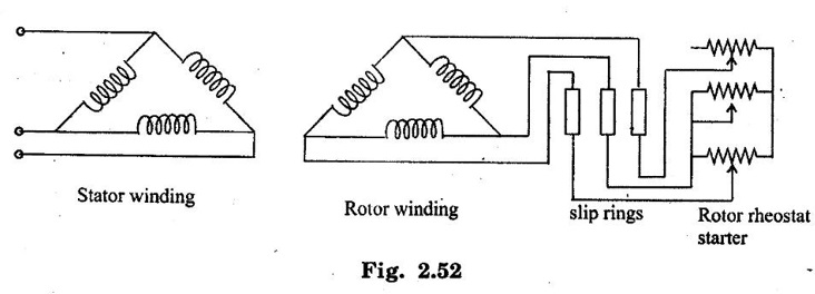
THREE PHASE INDUCTION MOTOR When a three phase balanced voltage is applied to a three phase balanced winding a rotating magnetic field is produced. This field has a constant magnetic and rotates in space with a constant speed. If a stationary conductor is placed in this field, an emf will be induced in it. By creating a closed path for the induced current to flow, an electromagnetic torque can be exerted on the conductor. Thus, the conductors is put in rotation. The important parts of a three phase induction motor are schematically represented in fig. 2.47. Broadly classified, they are stator and rotor. Each of these is described below. ● Stator: This is the stationary part of the motor. It consists of an outer solid circular metal part called the yoke or fame and a laminated cylindrical drum called the stator drum. This drum has number of slots provided over the entire periphery of it. ● Required numbers of stator conductors are embedded in the slots. These conductors are electrically connected in series and are arranged to form a balanced three phase winding. The stator is wound to give a specific number of poles. The stator winding may be star or delta connected. ● Rotator: This is the rotating part of the induction motor. It is also in the form so slotted cylindrical structure. The air gap between stator and rotor is as minimum as mechanically possible. There are two types of rotors - squirrel cage rotor and slip- ring or wound rotor. ● Figure 2.48 shows the construction of a squirrel cage rotor, in this type, each rotor slot accommodates a rod or bar made of a good conducting material. These rotor rods are short circuited at both ends by means of end rings made of the same metal as that of the rotor conductors. Thus, the rotor circuit forms a closed path for any current to flow through. ● Figure 2.49 shows the rotor winding of a slip ring or wound rotor. In this case, large number of conductors are embedded in the rotor slots. These conductors are electrically connected to form a balanced three phase winding. Again, the rotor is wound to give the same number of poles as the stator. Three similar ends of the rotor winding are joined together thus making a common point. The other three ends are connected to three slip rings which are mounted to the shaft. These slip rings are used to create a short circuit among the three phase windings of the rotor. A three phase balanced voltage is applied across the three phase balanced stator winding. A rotating magnetic field is produced. This magnetic field completes its path through the stator, the air gap and the rotor. In this process, the rotor conductors, which are still stationary, are linked by the time varying stator magnetic field. Therefore, an emf is induced in the rotor conductors. When the rotor circuit forms a closed path, a rotor current is circulated. Thus, the current carrying rotor conductors are placed in the rotating magnetic field. Hence, as per the law of interaction, an electromagnetic force is exerted on the rotor conductors. Thus, the rotor starts revolving. According to Lenz's law, the nature of the rotor induced current is to oppose the cause producing it. Here the cause is the rotating magnetic field. Hence, the rotor rotates in the same direction as that of the rotating magnetic field. In practice, the rotor speed never equals the speed of the rotating magnetic field (called the synchronous speed). The difference in the two speeds is called slip. The current drawn by the stator is automatically adjusted whenever the motor is loaded. If a 3-phase induction motors is directly switched on to the supply, they draw starting current equal to 5 to 8 times of full load current and develop starting torque equal to only 1 to 1.5 times of load torque. This amount of starting current is objectionable because it affects the system voltage momentarily. The starting torque developed may not be sufficient to accelerate the loads which are at rest. To limit the starting current and to improve the starting torque, 3-phase induction motors are started by means of suitable starters. However small capacity (upto 5 HP) motors can be started by using direct on line starters or directly switched on to the supply). 3-phase Squirrel Cage Induction Motor: The following are the different methods by which 3-phase squirrel cage induction motors can be started. (i) Primary resistor or reactor starters (ii) Auto-transformer starter (iii) Star-Delta (Y - Δ) starters In all the above three methods reduced voltage is applied to the terminals of starter winding. Once the motor picks up speed, then normal voltage is applied to the motor. The working of Y - Δ starter is explained here. Star-Delta (Y - Δ) Starter: This starter is used for induction motor, which is normally working on delta connected stator winding. This starter is having a TPDT switch and TPST switch. The necessary wiring of Y - Δ starter is with the starting winding of induction motor is shown in figure 2.50. The supply is given to the motor by closing the TPST switch. The starter handle i.e. TPDT switch is put on "start" position. Now the starter winding is connected to the supply in star connection. So, the starting current is reduced by 1/3 times the starting if the motor is directly switched on. This is well explained in fig. 2.51. The starting torque developed is about 1.5 to 2 times the full load torque. Once the motor runs on normal speed, the TPDT switch can be put on "RUN" position, now the motor winding is connected in delta. Rotor Resistance Starter for 3-phase Slip Ring Induction Motor : The connection of rotor resistance starter with rotor windings of a 3-phase slip ring induction motor is shown in figure 2.52 The normal voltage is applied to the starter windings, keeping the starter resistance at maximum or "start" position. The motor current and hence the supply current is controlled by this resistance. With starting resistance in the rotor circuit, the rotor power factor is increased. This increase the starting torque developed is proportional to the rotor power factor. When motor speed reaches the normal value, the starter resistance can be gradually cut so that rotor winding is short circuited through the slip rings.1. Principle
2. Construction
3. Working
4. Starting of 3-phase Induction Motors
Basic Electrical and Electronics Engineering: Unit II: Electrical Machines : Tag: : Construction, Operation Working Principle, Starting Method - Three Phase Induction Motor
Related Topics
Related Subjects

Basic Electrical and Electronics Engineering
BE3251 2nd semester Mechanical Dept | 2021 Regulation | 2nd Semester Mechanical Dept 2021 Regulation

Basic Electrical and Electronics Engineering
BE3251 2nd Semester CSE Dept 2021 | Regulation | 2nd Semester CSE Dept 2021 Regulation