Engineering Graphics: Unit II (a): Orthographic Projection
Terminology
Orthographic Projection | Engineering Graphics (EG)
1) Orthographic: The meaning of the words, `Ortho' and `Graphic' are `Right-angle' and `Drawing' respectively.
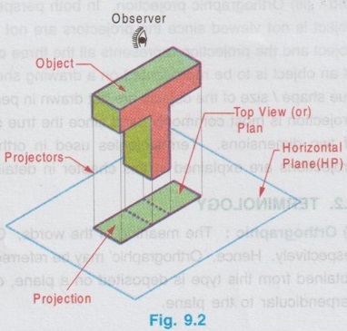
TERMINOLOGY 1) Orthographic: The meaning of the words, `Ortho' and `Graphic' are `Right-angle' and `Drawing' respectively. Hence, Orthographic' may be referred as `Right-angled drawing'. Therefore, the projection obtained from this type is deposited on a plane, obtained by the projectors which are right-angle (or) perpendicular to the plane. 2) Plane of Projection: A plane of infinite thickness and transparent on which the projection of an object is drawn is known as plane of projection. 3) Projection: The view (or) image of an object as observed by an observer and drawn on the plane of Front view projection is known as "Projection". 4) Object : A body for which the projections are to be drawn is known as object. The object may be of a machine, building (or) any body composed by a number of solids. 5) Observer: The person looking for the projections of an object is known as observer. In actual practice, observer is an Engineer / Draughtsman who prepares the drawings of an object. 6) Projectors: The projection of an object is drawn by means of straight lines, called visual rays. These lines (or) rays, visualised by the observer, parallel to each other and perpendicular to the plane are called as projectors. Fig. 9.1. shows the terminologies used in orthographic projection. It is to be noted that the image of the object looking from the position of observer is drawn on the transparent plane. The surface of the object, perpendicular to the plane cannot be visualised by observer. Also, the projectors are parallel to each other and perpendicular to the plane only when the observer is at infinite distance from the position of the object. 7) Vertical plane (V.P): A plane which is kept vertically to draw the projection of the object is known as vertical plane. The projection obtained on the vertical plane is known as `Front view' (or) Elevation. Vertical plane and Front view are shown in Fig. 9.1. 8) Horizontal plane (H.P): A plane which is kept horizontally to draw the projection of the object is known as Horizontal plane. The projection obtained on the horizontal plane is known as `Top view' (or) Plan. Horizontal plane and Top view are shown in Fig. 9.2. Refering the Fig. 9.1, the front view of the object is shown on the vertical plane. Front view is a two-dimensional figure in which length and height of the object can be measured, whereas the object kept in front of the vertical plane is a three-dimensional figure, having breadth, ie., the measurement perpendicular to the plane, which cannot be shown on the front view. Hence to observe the width of the object a horizontal plane may be used as shown in Fig. 9.2. Note: Two dotted lines shown in Topview indicates the hidden projection on the back side of the projection, observed from top. Construction of dotted lines in orthographic projections are explained in detail in article 9.10.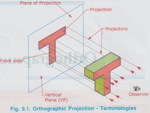
Engineering Graphics: Unit II (a): Orthographic Projection : Tag: : Orthographic Projection | Engineering Graphics (EG) - Terminology
Related Topics
Related Subjects

Engineering Graphics
GE3251 eg 2nd semester | 2021 Regulation | 2nd Semester Common to all Dept 2021 Regulation