Engineering Graphics: Unit III (b): Projections of Solids
Projections of Solids with Axis Inclined to VP and parallel to HP by Auxiliary plane method
Engineering Graphics (EG)
Note that after getting front view and top view in simple position, directly the final front view is obtained without the final top view, which is same as that obtained by change of position method.
PROJECTIONS OF SOLIDS WITH AXIS INCLINED TO VP AND PARALLEL TO HP BY AUXILIARY PLANE METHOD. Example 32: Draw the projections of a pentagonal prism of 30mm side base and axis 70mm lying on one of its longer edges on HP with one rectangular face perpendicular to HP such that the axis makes 60° with VP. This problem is already solved by change of position method. (Refer example 28) Now the projections are drawn by change of reference plane method. Step 1: Draw the reference line XY. Initially assuming the axis of prism is perpendicular to VP and resting on the ground by one of its longer edges draw the front view. Name the corners as 1', 2' etc., and a', b' etc., Step 2: Project the front view by drawing vertical projectors and draw the top view. Name the points elonio s as wely Inoit art waib buong arti no gnil bns as a, b etc., and 1, 2 etc. Step 3: It is given the axis is 60° with VP. Hence draw a new reference line X1Y1 at an angle of 60° to the top view of the axis and draw the projectors through the points a, b etc., and 1, 2 etc. in top view and perpendicular to X1Y1. Mark a point a'1 on the projector drawn through a such that the distance of a'1 from X1Y1 is equal to the distance a' in front view from XY. Similarly mark other points b'1, c'1 etc. and 1'1, 2'1 etc., and join the points to get final front view. (Fig. 14.53). Note that after getting front view and top view in simple position, directly the final front view is obtained without the final top view, which is same as that obtained by change of position method. Example 33: Draw the projections of a cylinder of diameter 45mm and axis length 75mm, lying on the ground with its axis inclined at 50° to VP and parallel to HP by change of reference line method. Step 2: Project the front view by drawing vertical projectors and draw the top view by naming the points a, b etc., and 1, 2 etc., Step 3: Draw a new reference line X1Y1 at an angle of 50° to the top view of the axis. Draw the projectors from various points in top view, perpendicular to the new reference line X1Y1. Mark the point a'1 on the projector drawn through a such that the distance of a'1 from X1Y1 is equal to that of a' in front view from XY. Similarly mark other points b'1, c'1 etc. and 1'1, 2'1 etc. and join all the points in proper sequence which is the required front view.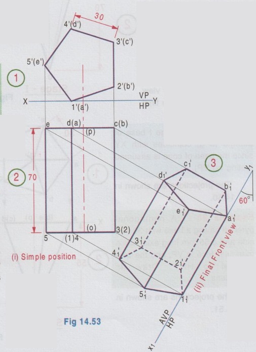
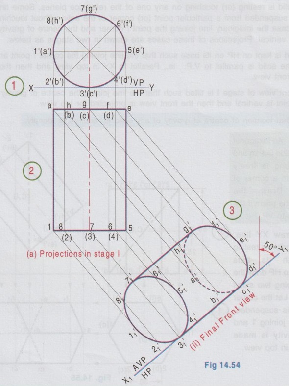 Step 1: Draw the reference line XY. Assuming the axis of cylinder is initially perpendicular to VP and lying on the ground draw the front view as a circle of 45mm diameter, touching the reference axis XY. Divide the circle into 8 equal parts and name the points as a', b' etc. and 1', 2' etc., (note that the hidden points are marked in the bracket).
Engineering Graphics: Unit III (b): Projections of Solids : Tag: : Engineering Graphics (EG) - Projections of Solids with Axis Inclined to VP and parallel to HP by Auxiliary plane method
Related Topics
Related Subjects

Engineering Graphics
GE3251 eg 2nd semester | 2021 Regulation | 2nd Semester Common to all Dept 2021 Regulation