Engineering Graphics: Unit III (b): Projections of Solids
Projections of Solids with Axis Inclined to HP and Parallel to VP by Auxiliary plane method
Engineering Graphics (EG)
Note that after getting front view and top view in simple position, directly the final top view is obtained without the final front view, same as that obtained by change of position method.
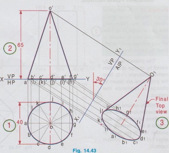
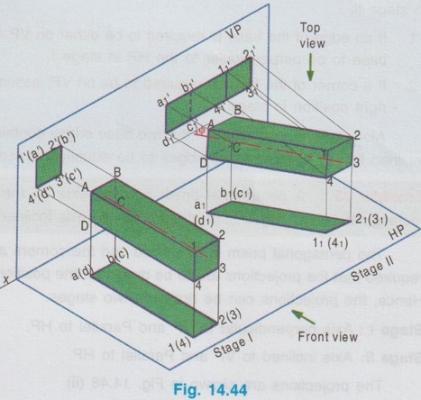
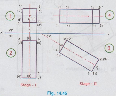
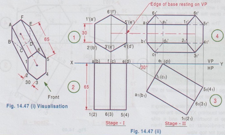
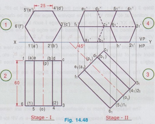
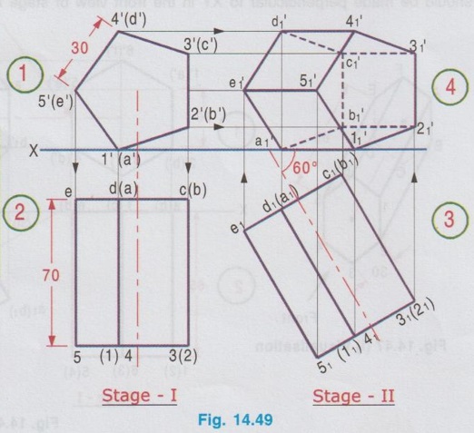
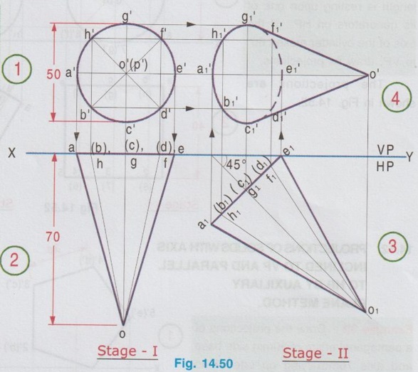
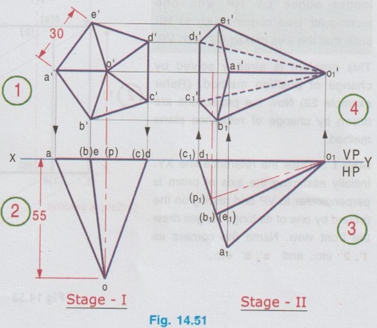
PROJECTIONS OF SOLIDS WITH AXIS INCLINED TO HP AND PARALLEL TO VP BY AUXILIARY PLANE METHOD. Example 23: A Hexagonal prism having base width 30mm side and 70mm long axis has an edge of its base on HP. Its axis is parallel to VP and inclined at 45° to HP. Draw its projections. This problem is already solved by change of position method (Example: 13). Now the projections are drawn by change of reference line method. Initially assume the axis is perpendicular to HP (ie., the plane about which axis of solid is to be inclined) and parallel to VP (as done in stage I of change of position method). Step 1: Draw the reference line XY. Draw the top view as hexagon, with an edge of base perpendicular to XY. (since the edge to lie on HP and about which the prism is to be tilted for final projections). Name the points as a, b etc. and 1, 2 etc.) Step 2: Project the top view and draw the front view having its bottom edge coincides with XY (since the prism is resting on HP). Name the points as a', b' etc., and 1', 2' etc. Step 3: Draw new reference line X1Y1 at 45° to the axis (since the axis is inclined at 45° to HP) at a convenient distance such that the final top view does not overlap with topview of stage 1). Mark VP and AIP, above and below the new reference line respectively. The final top view is to be drawn on the Auxiliary inclined plane ie., below the new reference line X1Y1. Draw the projectors through the points 1', 2' etc. and a', b' etc. in the front view, perpendicular to X1Y1. Mark points on these projectors from X1Y1 equal to their respective distances fromXY in the top view as a1, b1 etc. and 11, 21 etc. (For example, mark the point on the projector drawn through a' such that the distance of a1 from X1Y1 is equal to the distance of a' below XY). Similarly mark the points b1, c1 etc. and 11, 21 etc., Join the points thus obtained in proper sequence and complete the final top view as shown in Fig. 14.42. Note that after getting front view and top view in simple position, directly the final top view is obtained without the final front view, same as that obtained by change of position method. Example 24: Draw the projections of a cone of base diameter 40mm and axis length 65mm, resting on the ground with its axis inclined at 30° to the ground and parallel to VP. Step 1: Draw the reference line XY. Assuming the axis of cone is perpendicular to HP and parallel to VP, draw the top view as a circle. Divide the circle into 12 equal parts and name the points as a, b, c etc., Step 2: Project the top view by drawing vertical projectors and draw front view as a triangle, base coinciding with XY (since the base of cone is on HP). Name the points as a', b' etc., Step 3: It is given the cone is resting on ground and the axis is inclined to HP. Assume the cone is resting on 'g'. Draw a new reference line X1Y1 at an angle of 30° to the axis of cone in front view. Draw the projectors through the points a', b', c' etc., and perpendicular to the new reference line. Mark a point a1 on the projector drawn through a' such that the distance of a1 from X1Y1 is equal to that of the distance of a form XY. Similarly mark the points a2, b2 etc., and Join the points in proper sequence to get final top view (Fig. 14.43). Case 2b: Projections of solids with axis inclined to VP and Parallel to HP by change of position method. Let a square prism is inclined at an angle ϕ to VP and parallel to HP, for which the projections are to be drawn. The projections are drawn in two stages as below. Stage 1 : Axis perpendicular to VP and Parallel to HP. Stage II : Axis inclined at ϕ to VP and Parallel to HP. The pictorial view of square prism representing these two stages are shown in Fig. 14.44. In stage I, when the axis is assumed perpendicular to VP, the base is parallel to VP and hence the true shape and size can be drawn in front view. Top view will be a rectangle. Hence draw the front view first and then project the front view for topview. Then in stage II, tilt the axis to an angle ϕ with VP (ie the required inclination) but without affecting the position of axis with HP ie., keeping the axis again parallel to HP as shown in Fig. 14.44. As the axis is again made parallel to HP, the top view of stage I can be reproduced but with axis inclined at ϕ to XY. Then by projecting the topview the final front view can be drawn. Hence in stage II, draw the top view first and then draw the front view. The projections in stage I and stage II are presented below in Fig. 14.45. Note that the procedure of drawing projections in this case is just inverse of previous case 2(a). Note: When there are additional conditions to be satisfied along with axis being parallel to HP and inclined to VP, it is necessary that the initial position of the solid be so selected that when the solid is tilted from stage I to stage II, the lines and points will not change their relation with one of the reference planes, so that the shape of one of the views will remain the same. A general rule is that if the axis required to be parallel to HP and inclined to VP, all the given conditions with HP should be satisfied in stage I while all the conditions with VP should be satisfied in stage II. 1. If an edge of the base is required to be either on VP or parallel to VP, assume that edge of the base to be perpendicular to the HP in stage I. 2. If a corner of the base is required to be on VP, assume that corner to be at the extreme left or right position in stage I. Along with this condition, if the two base edges containing that corner are required to be equally inclined to VP, assume those edges to be equally inclined to HP in stage I. Example 25: A pentagonal prism of base side 25 mm and axis length 55 mm has one of its rectangular faces lying on the ground with its axis inclined at 40° to VP. Draw the projections. The pentagonal prism is visualised and the corners are named as shown in Fig. 14.46(i). It is required that the projections are to be drawn for the position of axis inclined to VP and Parallel to HP. Hence, the projections can be drawn in two stages. Stage I: Axis perpendicular to VP and Parallel to HP. Stage II: Axis inclined to VP and Parallel to HP. The projections are shown in Fig. 14.46 (ii) Step 1 (Front view): Draw the reference line XY. Draw a pentagon of side 25 mm as front view such that one of its rectangular faces, say the face 3'(c') 4'(d') is lying on the ground. Step 2 (Top view): Draw the vertical projectors from front view. Draw a horizontal line, parallel to XY, joining these projectors at any convenient distance below, which represents the distance of rear face of prism infront of VP. (If it is given in the problem it may be marked accordingly). Draw a rectangle as top view as shown in fig, measuring the axis length as 55 mm. Name the corners systematically. Step 3 (Top view): Now keeping the axis again parallel to HP, axis is tilted in such a way that it is inclined at 40° with VP. Hence topview shape will not be changed but its axis is making an angle of 40° with XY. Redraw the topview of stage I such that the edge b-e is nearer to the VP and the axis is inclined at 40° to VP. (Instead of the edge b-e, the edge 2-5 may also be made nearer to VP), and name the corners as a1, b1 etc. and 11, 21 etc., Step 4 (Front view): Draw the vertical projectors from top view and horizontal projectors from the front view of stage I. Mark the intersecting points as a'1, b'1 etc., and 11, 21 etc., Join visible edges with continuous lines and hidden edges with dashed lines following the rules of visibility. The topview and front view obtained in Stage II are the required projections. Example 26: A hexagonal prism having a base with 30 mm edge and 65 mm long axis, has an edge of its base in the VP such that the axis is inclined at 30° to VP and parallel to HP. Draw its projections. The hexagonal prism is visualised and the corners are named as shown in Fig. 14.47(i). Assume that the hexagonal prism has an edge d-e in VP for final position. Hence the edge DE should be made perpendicular to XY in the front view of stage I. Stage I: Axis is perpendicular to VP and Parallel to HP. Draw the front view first which gives, the true shape and size of the base, keeping the edge de perpendicular to XY. Then project the front view for corresponding top view. Stage II: Axis is inclined to VP and Parallel to HP Reproduce the top view from stage I but tilting the axis at an angle of 30° to XY. Then by projecting the corners vertically above XY and by projecting horizontally from front view of stage I, draw the final front view. The projections are shown in Fig. 14.47 (ii). Example 27 : A Hexagonal H of 15(e) prism, side of base 25 mm and axis 60 mm long, lies with one of its rectangular faces on HP, such that the axis is inclined at 45° to VP. Draw its projections. This problem is similar to example 25 but replace pentagonal prism by hexagonal prism. Stage 1 : Axis is perpendicular to VP and Parallel to HP Draw the front view first keeping a side coinciding with XY and then draw the top view. Stage II: Axis is inclined to VP and Parallel to HP. Redraw the top view from stage I with tilted axis position and then draw the final front view. The projections are shown in Fig. 14.48. Example 28: Draw the projections of a pentagonal prism of 30 mm side base and axis 70 mm long lying on one of its longer edges on HP with one rectangular face perpendicular to HP such that the axis makes 60° with VP. Stage I : Axis perpendicular to VP and parallel to HP. Draw the front view keeping a corner touching XY (since the longer edge is touching HP) and a side perpendicular to HP and then project for top view. Stage II: Axis inclined to VP and parallel to HP Redraw the top view of stage I with tilted axis position and then draw the final front view by drawing vertical projectors from top view and horizontal projectors from front view of stage I. The projections are shown in Fig. 14.49. Example 29 : A cone having 50 mm diameter and 70 mm long axis has a point of its base circle in VP such that the axis is inclined at 45° to VP and Parallel to HP. Draw its projections. Stage I: Draw the front view as a circle of diameter 50 mm and draw the corresponding top view as a triangle of altitude 70 mm. Stage II Tilt the top view of stage I such that the axis making an angle of 45° to XY and an end (say e) is touching XY. Draw the vertical projectors from top view and horizontal projections from front view of stage I, to draw the final front view. Note that in stage I base of triangle (a-g) coincides with XY since the base of cone is assumed resting on VP). The projections are shown in Fig. 14.50. Example 30: A pentagonal pyramid having a base with 30 mm side and a 55 mm long axis, has a triangular face in VP, and the axis parallel to HP. Draw its projections. The projections are shown in Fig. 14.51. Example 31: A cylinder disc of 60 mm diameter and 40 mm length is resting upon one of its generators on HP. If the axis of the cylinder makes 60° to VP, draw its projections. The projections are shown in Fig. 14.52.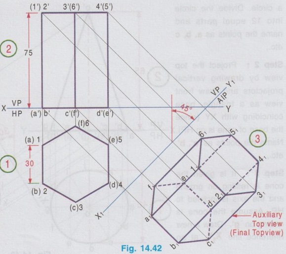


Engineering Graphics: Unit III (b): Projections of Solids : Tag: : Engineering Graphics (EG) - Projections of Solids with Axis Inclined to HP and Parallel to VP by Auxiliary plane method
Related Topics
Related Subjects

Engineering Graphics
GE3251 eg 2nd semester | 2021 Regulation | 2nd Semester Common to all Dept 2021 Regulation