Engineering Graphics: Unit III (b): Projections of Solids
Projections of Solids suspended from a point
Engineering Graphics (EG)
So far the projections of solids are drawn with the condition that a corner (or) an edge (or) a point of the solid is resting (or) touching on any one of the reference planes.
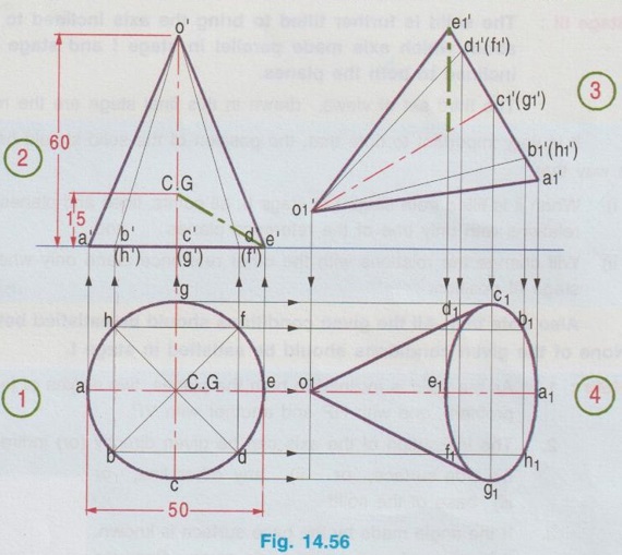
PROJECTIONS OF SOLIDS SUSPENDED FROM A POINT So far the projections of solids are drawn with the condition that a corner (or) an edge (or) a point of the solid is resting (or) touching on any one of the reference planes. Some times the solid may be freely suspended from a particular point (or) corner of the solid without touching any of the plane. In this case the imaginary line joining the point / corner and the centre of gravity of the solid will always be vertical. Projections of these cases are drawn in two stages as below. Stage I: Solid is kept on HP on its base such that the line joining the corner / point and the centre of gravity of the solid is parallel to V.P. ie., Parallel to XY in top view and then the top view is projected for front view. Stage II: Front view of stage I is tilted such that the line joining the centre of gravity of solid and the corner / point is vertical and then the front view is projected for top view. Note that location of centre of gravity of any solid is required to identify. Example 34: A Hexagonal prism of base side 30mm and axis 50mm long is freely suspended from a corner of one end. Draw the projections of the prism if the axis is parallel to VP. Step 1: Draw XY line. Assuming the prism is resting on HP with its axis perpendicular to HP draw the X top view, keeping two sides parallel to XY. Let the corner of left end 1 is suspended, hence the line joining 1 and centre of gravity is made parallel to XY in top view. Step 2: Project the top view and draw the corresponding front view. Mark the C.G at mid height, 25mm from base. Join 1' and C.G and extend to d'. Step 3: Tilt the front view of stage I such that 1' - C.G line is perpendicular to XY, since the solid is suspended about 1'. Note that the front view is drawn at a convenient height above XY, need not to touch XY since the solid is freely suspended about 1'. Step 4: Draw the vertical projectors through all the points from front view and draw horizontal projectors from top view of stage I to mark the intersecting points a1, b1 etc. and 11, 21 etc., Join these points in proper sequence to get the final top view. Example 35: Draw the projections of a cone of base diameter 50mm and height 60mm is freely suspended from one of its base points such that its axis is parallel to VP. Step 1: Draw XY line. Initially assuming the cone is resting on HP, draw top view as a circle of diameter 50mm. Divide the circle into eight (or 12) equal parts and name the parts as a, b etc., Assume the cone is to be freely suspended from the base point e. Hence the line joining e and C.G. of cone is made parallel to XY in top view. Step 2: Project the top view and draw the corresponding front view. Mark the C.G at h/4. (ie., 60/4 = 15mm from base). Join C.G and e'. Step 3: Tilt the front view of stage I such that the line C.G - e' is perpendicular to XY, since the cone is suspended about e' (Front view can be drawn at convenient height above XY; need not to touch XY since the solid is freely suspended). Step 4: Draw vertical projectors from front view and horizontal projectors from top view of stage I and mark the corresponding intersecting points as a1, b1 etc., and join these points in proper sequence to get the required final top view.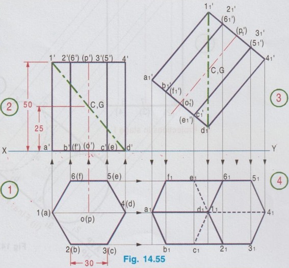
Engineering Graphics: Unit III (b): Projections of Solids : Tag: : Engineering Graphics (EG) - Projections of Solids suspended from a point
Related Topics
Related Subjects

Engineering Graphics
GE3251 eg 2nd semester | 2021 Regulation | 2nd Semester Common to all Dept 2021 Regulation