Engineering Graphics: Unit III (b): Projections of Solids
Projections of Solids in Simple Position
Engineering Graphics (EG)
If a solid is placed in first Quadrant such that its axis is perpendicular to one of the reference planes (HP, VP (or) PP) then the solid is said to be in simple position.
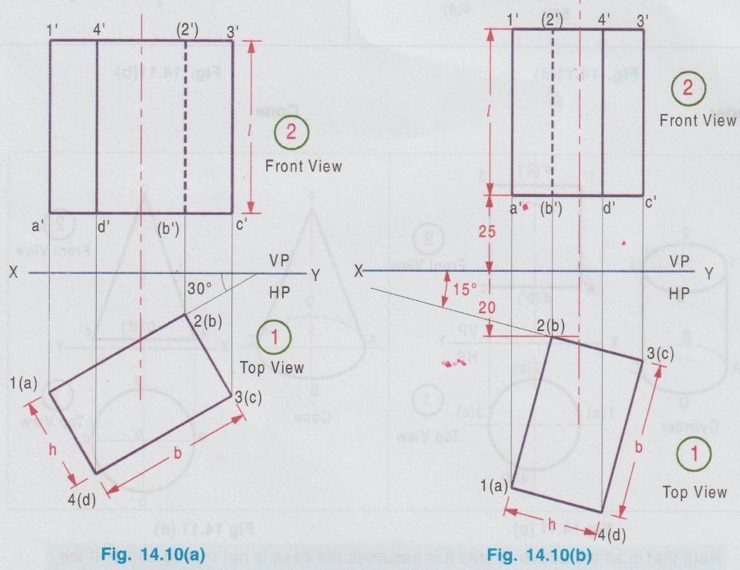
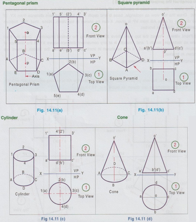
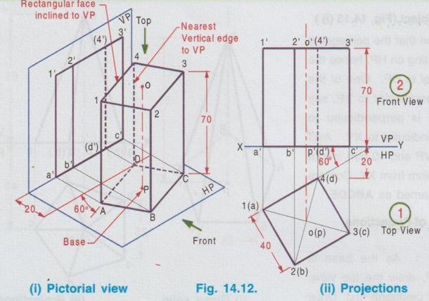
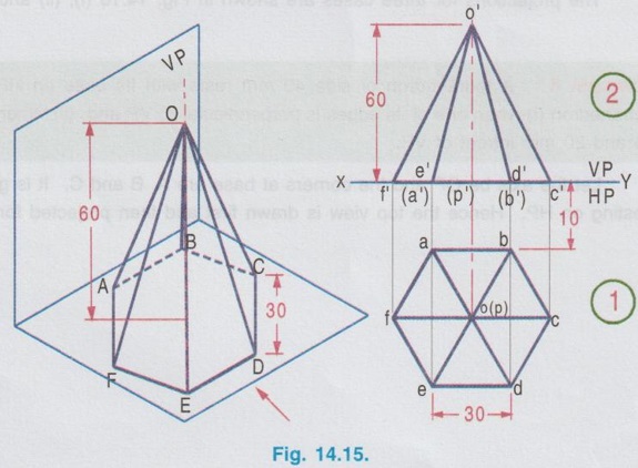
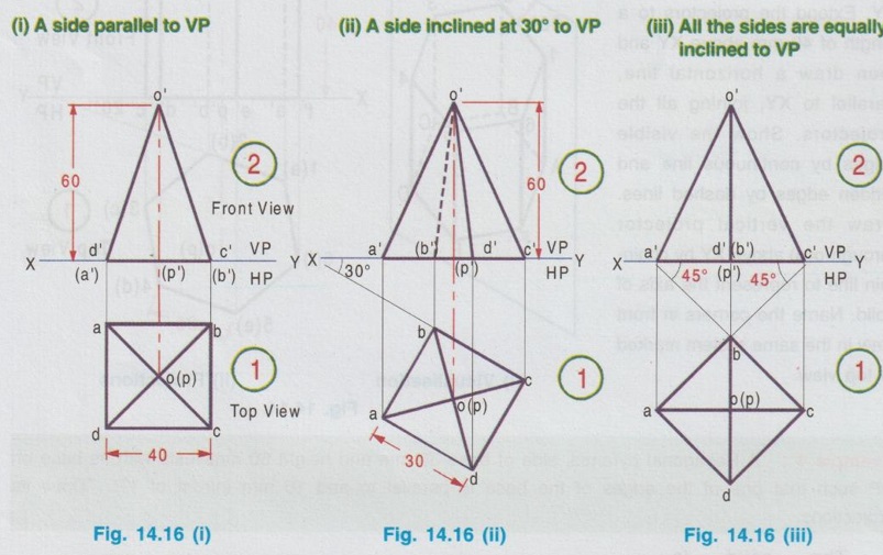
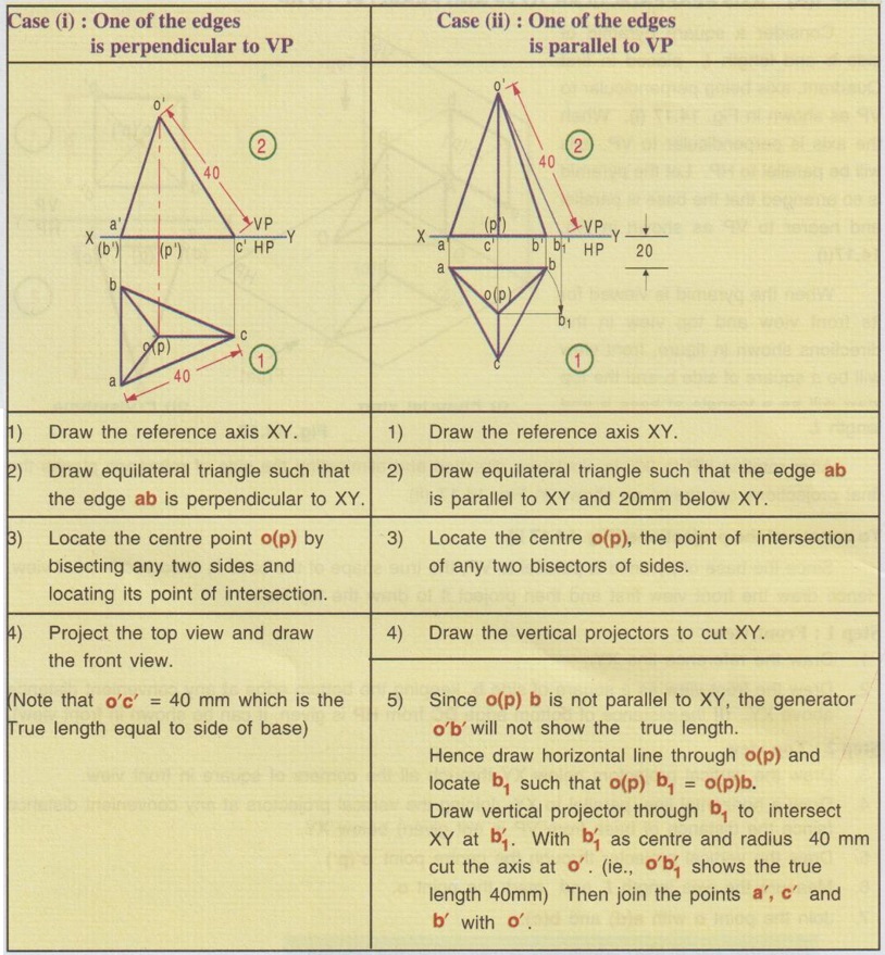
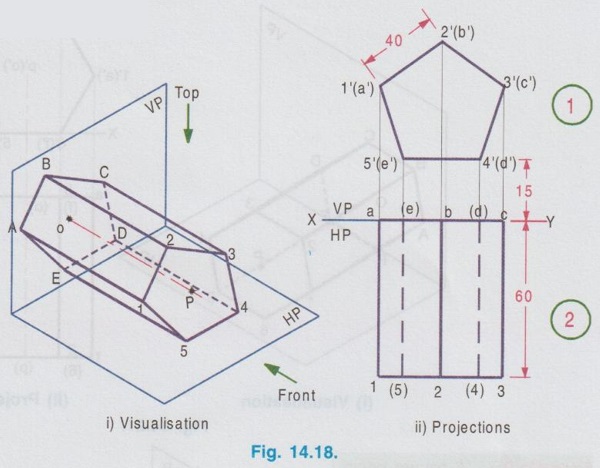
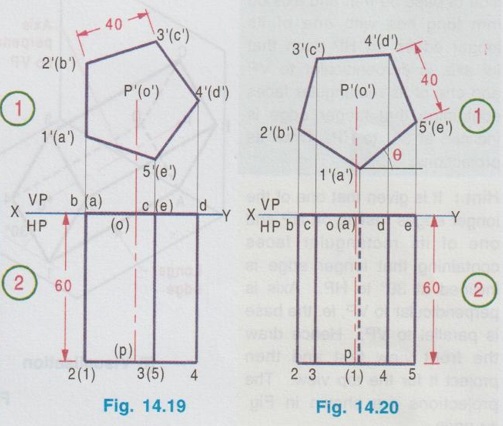
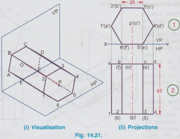
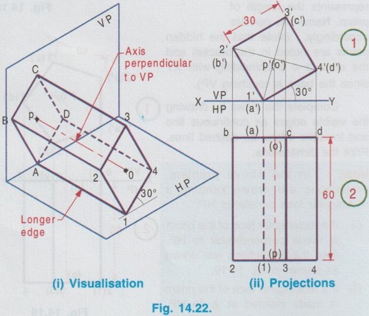
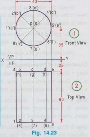
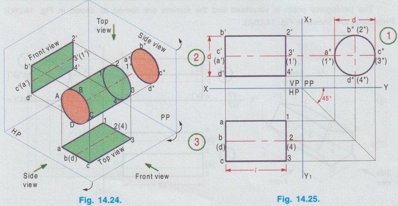
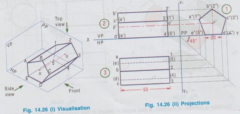
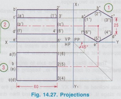
PROJECTIONS OF SOLIDS IN SIMPLE POSITION If a solid is placed in first Quadrant such that its axis is perpendicular to one of the reference planes (HP, VP (or) PP) then the solid is said to be in simple position. Because when the axis of solid is perpendicular to any plane, its base will be parallel to that plane, and hence its true shape and size can be seen on that plane. Therefore the view showing the true shape and size of the base is drawn first and then by projecting it to the other plane we get the related view. For example, if the axis of a solid is perpendicular to HP, then the base is parallel to HP. So draw the true shape seen on HP first, ie., the top view and then project the top view for front view. Similarly, if the axis of a solid is perpendicular to VP, then the base is parallel to VP, So draw the true shape seen on VP first, ie., the front view and then project the front view for top view. Suppose if the axis of a solid is perpendicular to profile plane (PP), then the base is parallel to PP, so draw the true shape seen on PP first, ie the side view and then project the side view for top view and front view. Hence it is to be noted that one set of views will be sufficient to draw the projections of solids in simple position. The method of viewing the solids and presenting its projections in simple position are explained below. Consider a rectangular prism of length l, breadth b and depth h, placed in first Quadrant, axis being perpendicular to HP as shown in Fig. 14.9 (i). (Corners at bottom base are marked as A, B, C, D and the corners at top base are marked as 1, 2, 3, 4). When the axis is perpendicular to HP, it is evident that the base is parallel to HP. When the solid is viewed for its front view and top view in the directions shown in figure, top view will be a rectangle of base b and depth h and the front view will be a rectangle of length l and breadth b. HP is rotated to 90° in clockwise direction and the size of reference planes is deleted. The final projections are shown in Fig. 14.9. (ii). 1) Top view: Since the base is parallel to HP and true shape is seen in top view, draw the top view first. Draw the top view as rectangle, base b and depth h at any convenient distance from XY. (If the distance of edge AB from VP is given, it can be shown in top view). Note that the hidden corners are shown in bracket. 2) Front view: Project the top view above XY by drawing the vertical projectors. Draw the front view as rectangle, length l and breadth b at any convenient distance above XY (If the distance of bottom base from HP is given, it can be shown in front view). Note that the hidden corners are shown in bracket. Complete the views and dimensioning. Note: 1. If it is given as, the axis perpendicular to HP while the edge AB is making an angle 30° with VP, then the projections are drawn as below [Fig. 14.10(a)]. 2. If it is given as, axis perpendicular to HP while the corner B is at 20 mm from VP and the base is 25 mm above HP and the edge BC is making an angle 15° with VP, then the projections are drawn as above [Fig. 14.10(b)]. Similarly the projections of other solids in simple position (Perpendicular to HP) can be drawn. Few examples are given below in Fig. 14.11. Note that in all the above figures it is assumed the base is not resting on HP. If the base is resting on HP, then bottom line of front view must coincide with xy. It is noted that if orientation of base / edge is given with respect to the HP/VP, it is to be shown in respective projections. ie., In Fig. 14.11(a), one of the vertical edges of vertical faces of pentagonal prism is parallel to VP and nearer to observer. In Fig. 14.11(b), two base edges of the pyramid are parallel to VP. Example 1: A square prism of 40 mm side and 70 mm height is resting on HP with one of its rectangular faces inclined at 60° to VP. If the nearest vertical edge is 20 mm infront of VP, draw its projections. Pictorial view showing the position of prism in first Quadrant and the directions for front view and top view are shown in Fig. 14.12(i). Rotating HP to 90° and eliminating size of planes, the final projections are shown in Fig. 14.12(ii). 1) Top view: Draw the top view which shows the true shape and size, a square of 40 mm side with one side inclined at 60° to XY such that the nearest edge is 20 mm from xy which represents the distance of vertical edge from VP. Mark the axis position by drawing a cross mark in the direction of the diagonals of the square. Name the corners and indicate the hidden edges in the bracket. 2) Front view : 1. Draw the vertical projectors through all the corners of the square in top view, to a height of 70 mm (ie length of prism). Since the prism is resting on HP, bottom edge of front view coincides with XY. 2. Draw the upper edge as a straight line, 70 mm above XY, parallel to XY and joining the projectors drawn from top view. 3. Name the corners corresponding to the names given in the top view. Draw the axis o'p' in front view by projecting from the point o(p). 4. Finish the views by showing visible and outline by thicklines, short dashed line for hidden edges and chain line for axis. 5. Print the given dimensions and complete the projections. Note : Examination point of view, draw only the projections, Pictorial view need not be drawn. However, free hand sketch may be drawn for the solid with proper numbering and then draw the projections, as explained in the following examples. Example 2: A pentagonal pyramid of 25 mm side and 65 mm long is resting upon its base on HP such that one of the base edges is perpendicular to VP. If the axis of the pyramid is perpendicular to HP and parallel to VP and 40 mm away from VP, draw the projections. It is given that the pentagonal pyramid is resting on HP, hence the base is parallel to HP. One of the edges is perpendicular to VP, say the edge AE is perpendicular to VP ie., Perpendicular to XY. Axis is parallel to VP and 40 mm infront of VP, ie., 40 mm from XY. Corners in base are named as ABCDE. 1) Top view : As the base is parallel to HP, draw the top view, true shape of pentagon first. Draw the vertical edge ae of 25 mm long. Construct a pentagon by any method taking the side ae as one of the edges. Locate the centre point of pentagon, o(p). Draw the reference line XY such that it is perpendicular to ae and 40 mm above o(p). Name the corners of pentagon in top view as abcde. 2) Front view: Draw the vertical projectors from top view to intersect the reference axis at e'(a'), d'(b') and c'. Draw the vertical projector through the point o(p) to intersect the reference axis XY at p'. Draw vertical line through p' and mark apex o' such that p'o' = 65 mm. Join the points e'(a), d'(b') and c' with o'. Complete the view, name the corners and print the dimensions. Example 3: A Hexagonal prism of side 25 mm, axis 40 mm long is resting on HP on its base, axis being perpendicular to HP and parallel to VP. Draw the projections if one of the edges of the base is inclined at 20° to VP. 1) Top view: Draw the reference line XY. inclined at 20° to XY. Draw one of the edges say 1(a) 2(b) of 25 mm long Taking the line 1(a) 2(b) as one of the sides construct a hexagon by any method. (As the distance of the corner B from VP is not given it can be assumed suitably.). Name the corners of the pentagon in top view indicating the hidden points in the bracket and mark the centre point of hexagon as o(p). 2) Front view: Draw vertical projectors through the corners from top view to reference axis XY. Extend the projectors to a length of 40 mm above XY and then draw a horizontal line, parallel to XY, joining all the projectors. Show the visible edges by continuous line and hidden edges by dashed lines. Draw the vertical projector through o(p) above XY by chain- thin line to represent the axis of solid. Name the corners in front view in the same system marked in top view. Example 4: A Hexagonal pyramid, side of base 30 mm and height 60 mm rests with its base on HP such that one of the edges of the base is parallel to and 10 mm infront of VP. Draw its projections. The solid is visualised as shown in Fig. 14.16(i) and the projections are shown in Fig. 14.15(ii). Top view as a hexagon is drawn first, keeping one of the base edges (say the edge ab) is parallel to and 10mm from VP and then the front view is drawn by projecting the top view. Note that all the corners in top view are joined with centre O, which shows the top view of slant surfaces of pyramid. Example 5: A Square pyramid having base with 40 mm side and 60 mm axis is resting on its base on HP. Draw the projections when (i) a side of the base is parallel to VP (ii) a side of the base is inclined at 30° to VP (iii) all the sides of the base are equally inclined to VP. The projections for three cases are shown in Fig. 14.16 (i), (ii) and (iii) respectively. Example 6: A tedrahedron of side 40 mm rests with its base on HP. Draw the projections of tetrahedron (i) when one of its edges is perpendicular to VP and (ii) When one of its edges is parallel to and 20 mm infront of VP. Let the axis be OP and the corners at base are A, B and C. It is given that the tetrahedron is resting on HP. Hence the top view is drawn first and then projected for front view. Consider a square pyramid of side b and length l, placed in first Quadrant, axis being perpendicular to VP as shown in Fig. 14.17 (i). When the axis is perpendicular to VP, axis will be parallel to HP. Let the pyramid is so arranged that the base is parallel and nearer to VP as shown in Fig. 14.17(i) When the pyramid is viewed for its front view and top view in the directions shown in figure, front view will be a square of side b and the top view will be a triangle of base b and length l. After rotating HP to 90° in clockwise direction and eliminating the size of reference planes the final projections are drawn as shown in Fig. 14.17 (ii). Since the base of pyramid is parallel to VP, the true shape of the base is observed in front view. Hence draw the front view first and then project it to draw the top view. Step 1: Front view 1. Draw the reference line XY. 2. Draw the front view as a square of side b, keeping the bottom edge at any convenient distance above XY. (If the distance of bottom edge DC from HP is given, it can be shown in front view). Step 2: Top view 3. Draw the vertical projectors below XY through all the corners of square in front view. 4. Draw a horizontal line, parallel to XY, Joining the vertical projectors at any convenient distance (since the distance of base from VP is not given) below XY. 5. Draw the vertical projector through the centre point o'(p'). 6. Measure the axis length l and mark the point o. 7. Join the point o with a(d) and b(c). Note that the hidden edges are shown within the bracket. Example 7: A pentagonal prism having a base with 40 mm side and 60 mm long axis, has one of its bases in VP. Draw the projections of prism when a rectangular face is parallel to and 15 mm above HP. It is given that a base of the prism is in VP (ie., parallel to VP), hence the front view will show the true shape and size of the prism. Hence draw the front view first and then draw the top view. The prism is visualised and the corners are named as shown in Fig. 14.18 (i) and the projections are shown in Fig. 14.18(ii). Step 1 (Front view) : Draw a side of pentagon (say the side ED) as parallel to XY and then construct the Pentagon. Name the corners of pentagon. Edge 5'(e') - 4'(d') is 15 mm above XY which represents the height of rectangular face above HP. Step 2 (Top view) : Draw the vertical projectors through the corners to intersect XY. Extend the lines to 60 mm long from XY which represents the length of prism. Name the corners accordingly. (Note that the hidden points are noted in the bracket and the edge a-c is coinciding with XY since the base is touching VP). Complete the views by drawing the visible edges as continuous line and invisible edges as dashed lines. Print the dimensions. Note: In the above problem, projections are drawn keeping a rectangular face parallel to HP. (i) If a rectangular face of the prism is made perpendicular to HP, then the projections are drawn as shown in fig. 14.19. (ii) If a rectangular face of the prism is made inclined at θ to HP, then the projections are drawn as shown in fig. 14.20. Example 8: A hexagonal prism, side of base 25 mm and axis 65 mm long, lies with one of its rectangular faces on HP and the axis is perpendicular to VP. Draw its projections. Hint: Axis is perpendicular to VP, hence base is parallel to VP. One of the rectangular faces on HP, hence the bottom edge of front view coincides with XY. True shape and size of base is seen in Front view. Hence draw the front view first and then project it for top view. Corners are named and the object is visualised as shown in Fig. 14.21(i) and the projections are shown in Fig. 14.21(ii). Example 9: A square prism, side of base 30 mm and axis 60 mm long lies with one of its longer edges on HP such that its axis is perpendicular to VP and one of its rectangular faces containing that longer edge is inclined at 30° to HP. Draw its projections. Hint: It is given that one of the longer edges resting on HP and one of its rectangular faces containing that longer edge is inclined at 30° to HP. Axis is perpendicular to VP, ie. the base is parallel to VP. Hence draw the front view first and then project it for the top view. The projections are shown in Fig. 14.22(ii). Example 10: Draw the projections of a cylinder 40 mm diameter and axis 80 mm long, axis being perpendicular to VP and one of the bases is 25 mm infront of VP. The axis of cylinder is 35 mm above HP. The axis of cylinder is perpendicular to VP ie., base is parallel to VP. Hence true shape of the base is seen in front view. In front view centre of circle is 35 mm above XY which represents the height of axis above HP. The projections are shown in Fig. 14.23. Note: 1. For the position of cylinder in simple position (ie. perpendicular to any reference plane) the circumference of circle need not be divided to draw the generators. The projectors can be drawn directly. But at later stage, when the position of cylinder is tilted in such a way that making an angle with any x- plane, divisions on circumference is necessary to draw the projections. 2. For simple position the circumference of circle may be divided into minimum number of divisions (sayin 4), but for the position of cylinder tilted about any plane, it is suggested to divide the circumference into 8 (or) 12 equal divisions for obtaining smooth curve. If the axis of a solid is parallel to both HP and VP it is evident that the axis is perpendicular to profile plane (PP). Also the true shape and size of the base is seen only in the projection on PP, ie., side view. Hence it is suggested to draw the side view first and then the side view is projected for front view and top view by using mitre line. Consider a cylinder of diameter, d and length l placed in first Quadrant, axis being parallel to both horizontal and vertical planes. ie, axis is perpendicular to the profile plane (PP) as shown in Fig. 14.24. Since the axis is perpendicular to PP, the true shape and size is seen in side view (ie. projection on PP). It is a circle of diameter d. Hence the side view to be drawn first. When the cylinder is viewed for its front view and top view in the directions shown, the front view is a rectangle of length l and height d. Similarly the top view is also a rectangle of length l and breadth d. After getting the projections on three reference planes, HP is rotated to 90° in clockwise direction and the PP is rotated to 90° in anticlockwise direction to get HP below VP and PP adjacent to VP. After eliminating the size of reference planes, the projections are drawn as shown in Fig. 14.25. Construction of Projections (Fig. 14.25) Step 1 (Side View): Draw the reference line XY. Draw the reference line (vertical) X1Y1 perpendicular to XY. Draw the side view, circle of diameter d. Name the points on circumference as a", b", c" and d" and the corresponding hidden points are marked as 1", 2", 3" and 4" within the bracket. Step 2 (Front view): Draw the horizontal projectors through the points on the circumference of circle. At a convenient distance draw the vertical edges of front view 2'4' and b'd', at l distance apart, which representsd the length of cylinder. Step 3 (Top view): Draw mitre line at an angle of 45°. Draw vertical projectors from side view to intersect the mitre line and then draw the horizontal projectors through the points of intersection of vertical projectors with mitre line. Draw vertical projectors from front view and complete the top view. Example 11 : A pentagonal prism having a 20 mm edge of its base and an axis of 50 mm length is resting on one of its rectangular faces with the axis perpendicular to the profile plane. Draw the projections of the prism. The pentagonal prism is visualised and the corners are named as shown in Fig. 14.26(i). Projections are shown in Fig. 14.26(ii). Step 1 (Side view): Draw the reference lines XY and X1Y1. Draw a pentagon of corners a", b" etc., such that one of the edges (say e"d") coincides with XY and locate the centre of pentagon. Step 2 (Front view) : Draw the horizontal projectors through the corners and centre point. At any convenient distance from X1Y1 draw the right edge of front view 2'4'. Draw the left edge of front view b'd', 50 mm from right edge which represents the length of prism. Step 3 (Top view): Draw the vertical projectors from the side view to intersect the mitre line and through the points of intersection draw the horizontal projectors. Draw the vertical projectors from front view to intersect the horizontal projectors drawn from mitre line and locate the points of intersections. Complete the top view and name the points as shown in figure. Print the dimensions and complete the projections. Example 12 : A Hexagonal prism side of base (2 25 mm and axis 60 mm long lies with one of its longer edges on HP and its axis parallel to both HP and VP. Draw its projections. The projections are shown in Fig. 14.27.Case 1 a) Axis perpendicular to HP and Parallel to VP.
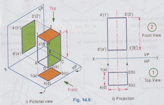
To construct the projections (Fig. 14.9. (ii) )
Construction of Projections
Naming the object (Fig. 14.13 (i) )
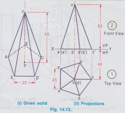
Construction of Projections (Fig. 14.13 ii)
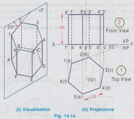
Construction of Projections (Fig. 14.14 ii)
CASE 1(B): AXIS PERPENDICULAR TO VP AND PARALLEL TO HP.
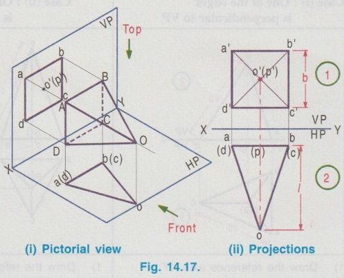
To construct the projections (Fig. 14.17 ii)
Construction of Projections (Fig. 14.18 ii)
CASE 1(C): AXIS PARALLEL TO BOTH HP AND VP
Engineering Graphics: Unit III (b): Projections of Solids : Tag: : Engineering Graphics (EG) - Projections of Solids in Simple Position
Related Topics
Related Subjects

Engineering Graphics
GE3251 eg 2nd semester | 2021 Regulation | 2nd Semester Common to all Dept 2021 Regulation