Engineering Graphics: Unit II (d): Projections of Planes
Projections of planes inclined to Both HP & VP
Engineering Graphics (EG)
A plane figure which is inclined to both HP & VP may be grouped into two categories as below:
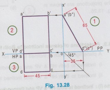
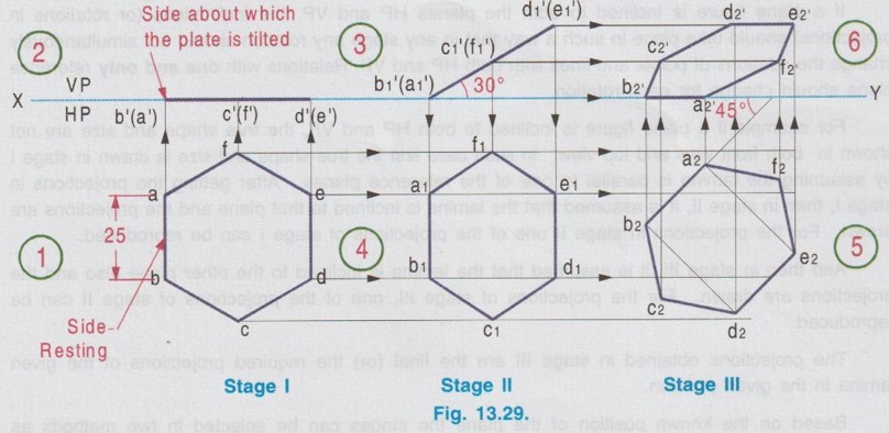
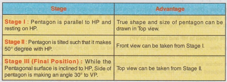
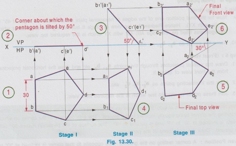
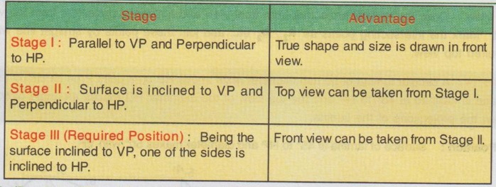
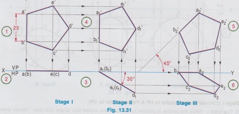
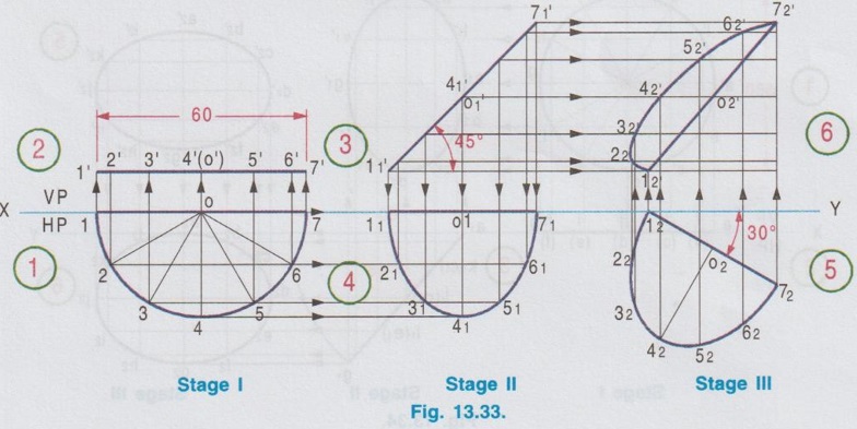
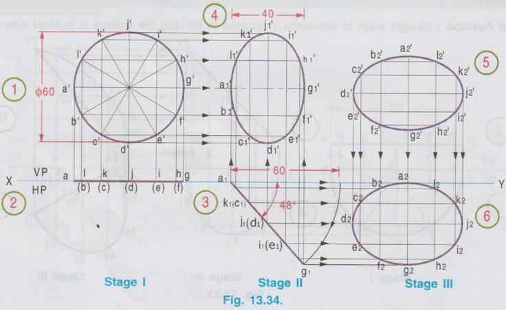
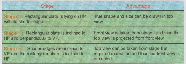
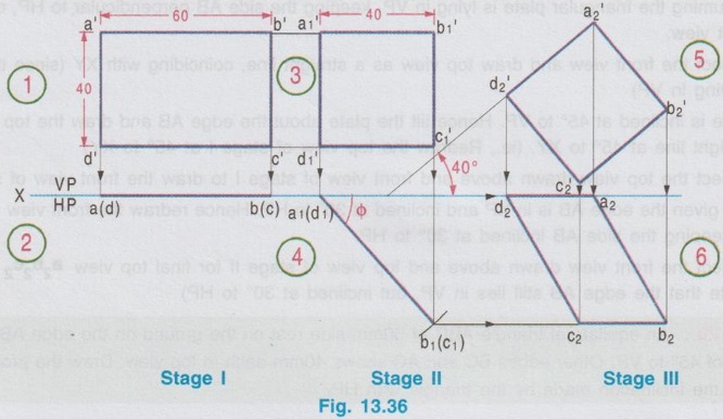
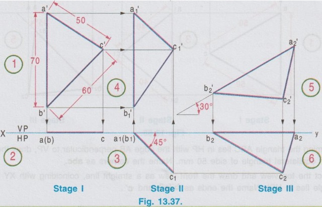
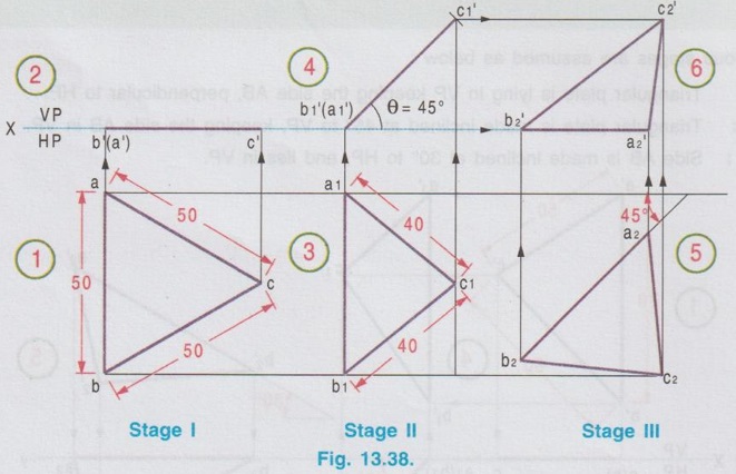
Projections of planes inclined to Both HP & VP A plane figure which is inclined to both HP & VP may be grouped into two categories as below: i) Inclined to both HP & VP and perpendicular to Profile Plane (PP). ii) Inclined to both HP & VP and Inclined to Profile Plane (PP). Case (i): Inclined to both HP & VP and Perpendicular to Profile Plane (PP) Consider a plane lamina inclined to both reference planes but perpendicular to profile plane as shown in Fig. 13.27 (i). When the plane lamina is viewed, size is reduced in both front view and top view as it is inclined to both horizontal and vertical planes. But the side view of the lamina is a straight line as it is perpendicular to the profile plane (PP). In such cases the side view may also be included in orthographic projections. To draw the projections of such cases it is suggested to draw the side view first and then project it to draw front view and top view. It is also noted that the traces of such cases in all the planes (VP, HP and PP) are straight lines. The trace on Profile plane is the side view of the plane figure itself. Note: The front view and top view may also be developed directly without side view. Example 10: A rectangular plate ABCD of size 45 x 65 mm is resting upon one of its shorter edges on HP and the other shorter edge on VP. If the plate is perpendicular to profile plane (PP) draw the projections. Assume the edge on HP is 35 mm away from VP. 1) Side view : Draw the vertical reference axis X'Y' to intersect XY at O. Locate the point d"(c"), 35 mm from X'Y' which represents the distance of edge DC on HP from VP. Taking d"(c") as centre and 65 mm radius cut the axis x'y' at a"(b"). 2) Front view : Draw the horizontal projector through a"(b"). Locate b' on the horizontal projector drawn through a" (b") at any convenient distance from X'Y' axis (since the distance of plane from PP is not given). Locate a' such that a' b' = 45 mm. Draw the vertical projectors through b' and a' to intersect the XY axis at c' and d' respectively. a' b' c' d' is the front view. 3) Top view: Draw the mitre line through O (ie, at 45°). Draw the vertical projector through d′′(c") to intersect the mitre line and then draw the horizontal projector to intersect b'c' line at c. Locate the point d such that dc = 45 mm and draw a vertical line through d to intersect XY axis at a. abcd is the top view. Case (ii): Inclined to both HP and VP and Inclined to PP. If a plane figure is inclined to both HP and VP and at the same time inclined to profile plane also, then the projections on these planes will not show its true size and shape but only its distored form. In such a case the side view of a plane figure is not drawn and the Front view and Top view are developed in three stages. Therefore in a problem, plane figure is inclined to both HP and VP (or) inclined to one plane but one of the edges make an angle with the another plane, (such problem is to be treated as plane figure inclined to all the three reference planes) the projections are drawn in three stages as below: Stage I : Lamina parallel to one reference plane. Stage II : Lamina inclined to one reference plane. Stage III : Lamina inclined to both the reference planes. It is important that the positions in three stages should be so selected that at the end of the third stage, projections are obtained for the required position. If a plane figure is inclined to both the planes HP and VP, the inclinations (or rotations in projections) should take place in such a way that in any stage any rotation should not simultaneously change the relations of points and lines with both HP and VP. Relations with one and only reference plane should change for each rotation. For example if a plane figure is inclined to both HP and VP, the true shape and size are not shown in both front view and top view. In such case first the true shape and size is drawn in stage I by assuming the lamina is parallel to one of the reference planes. After getting the projections in stage I, then in stage II, it is assumed that the lamina is inclined to that plane and the projections are drawn. For the projections in stage II one of the projections of stage I can be reproduced. And then in stage III, it is assumed that the lamina is inclined to the other plane also and the projections are drawn. For the projections of stage III, one of the projections of stage II can be reproduced. The projections obtained in stage III are the final (or) the required projections of the given lamina in the given position. Based on the known position of the plane the stages can be selected in two methods as detailed below: In Method I: i) Reproduce Top view of Stage I to Top view of Stage II with rotation, and then ii) Reproduce Front view of Stage II to Front view of Stage III with rotation. Similarly in Method II: i) Reproduce Front view of Stage I to Front view of Stage II with rotation, and then ii) Reproduce Top view of Stage II to top view of Stage III with rotation. Note: Always consider the tilting of given plane surface in stage II and tilting of one of the edges of plane surfaces in stage III. Example 11: A Hexagonal plate of size 25 mm rests on HP on one of the sides inclined at 45° to VP. The surface of the plate makes an angle of 30° with HP. Draw the front view and top view of the plate. Here the surface of plate makes an angle (30°) with HP and at the same time one of the edges makes an angle of 45° to VP. Hence this problem is treated as a plane figure inclined to both HP and VP and hence three stages are followed to draw its projections. Assume the plate is lying on HP (ie parallel to HP) with one of its sides perpendicular to VP. Assume the plate is tilted such that the surface of plate makes an angle of 30° with HP. Assume the edge about which the plate was tilted in second stage is making an angle of 45° with VP and then draw the final projections. Step 1: (Top view) 1. Draw the reference line XY. 2. Assuming the plate is lying on HP draw the hexagon (true shape and size) such that one of its edges is perpendicular (say the edge AB) to VP (ie, XY). Step 2: (Front view) 3. Draw the front view as a straight line on XY (since plate lies on HP) 4. Name the points in front view and top view. Step 3: (Front view) 5. Reproduce the front view of Stage I by tilting it at an angle of 30° to XY (since the surface is inclined at 30° to HP). Name the points b'1(a'1), c'1(t'1) and d'1(e'1). Step 4: (Top view) 6. Draw the vertical projectors from front view and horizontal projectors from the top view of Stage I. 7. Mark the intersecting points as a1, b1 etc. 8. Join these points by a straight line which is the top view in Stage II. Step 5: (Top view) 9. Now for the final position one of the edges of hexagonal plate should make an angle of 45° to VP (ie, with XY). Hence Redraw the top view of Stage II but making the edge about which Hexagon was tilted (ie, the edge AB) 45° with XY which is the required top view. 10. Name the points as a2, b2, … etc. Step 6: (Front view) 11. Draw the vertical projectors through the points a2, b2, etc and draw the horizontal projectors from the front view of Stage II. 12. Mark the intersecting points as a'2, b'2, c'2 etc. 13. Join these points by straight line which is the required front view. Example 12: A pentagon of side 30 mm rests on the ground on one of its corners with the sides containing the corner being equally inclined to the ground. The side opposite to the corner on which it rests is inclined at 30° to VP and is parallel to HP. The surface of the pentagon makes 50° with the ground. Draw the projections of the pentagon. Given Position: A corner resting on the ground; side opposite to that corner is inclined at 30° to VP; Surface makes 50° with HP. Different Stages considered Pentagon is inclined to HP. Hence in stage I it is made parallel to HP. 1) Top view : Draw the pentagon of side 30 mm below XY which is the top view of stage I. True shape and size can be shown since the pentagon is assumed parallel to HP. Keep one of the vertices on right side, assumed to rest on HP in stage II. Name the points as a, b, c, d, e. 2) Front view: Draw the front view as a straight line on XY (since the pentagon lies on HP) by projecting the top view. Name the points as b'(a'), c'(e') and d'. 3) Front view: Assume the Pentagon is tilted about the corner D such taht it makes 50° to HP. Hence reproduce the front view of Stage I by tilting it to the angle of 50° with XY. Name the points as b'1(a'1), c'1(e'1) and d'1. 4) Top view : Draw the vertical projectors from the front view and draw the horizontal projectors from the top view of stage I. Mark the intersecting points as a1, b1, c1, d1 and e1. Join these points by straight line which is the top view in Stage II. 5) Top view: Already the pentagon is made inclined at 50° to HP in stage II. Now the side opposite to the corner about which pentagon was tilted (ie, the edge AB) should make an angle of 30° to VP. Hence redraw the top view of stage II by keeping the side a1, b1 at an angle of 30° with XY which is the required top view. Name the points as a2, b2, c2, d2 and e2. 6) Front view: Draw the vertical projectors from the top view and draw the horizontal projectors from the front view of Stage II. Mark the intersecting points as a'2, b'2, c'2, d'2 and e'2 and join these points by straight line, which is the required front view. Example 13: A Pentagonal sheet of side 25 mm is having its surface inclined at 30° to VP. One of its sides is parallel to VP and inclined to HP at an angle of 45°. Draw the projections. Given Position: Surface of Pentagon is inclined to VP and one of its sides is inclined to HP. Stages considered: Pentagon is inclined to VP. Hence it is made parallel to VP in stage I. 1) Front view: Draw the Pentagon of side 25 mm such that one side (say AB) is perpendicular to XY, which is the front view of Stage I. 2) Top view: Draw the top view as a straight line on XY (Assume the pentagon lies on VP) and name the points. 3) Top view: Assume that the pentagon is tilted about the edge AB at an angle of 30° to VP. Hence redraw the top view of stage I, by tilting about the point a(b) to an angle of 30°, which is the top view of stage II. Name the points as a1, (b1) etc. 4) Front view: Draw the vertical projectors from top view and horizontal projectors from the front view of stage I. Mark the intersecting points as a'1, b'1 etc., and join these points by straight line which is the front view of stage II. 5. Front view: Already the pentagon is inclined to VP in stage II. Now, assume the edge about which pentagon was tilted (ie edge AB) for stage II is now inclined at 45° to HP. Hence redraw the front view of stage II by keeping the edge AB making 45° with HP. Name the points as a'2, b'2 etc. which is the required front view. 6) Top view: Draw the vertical projectors from front view and horizontal projectors from top view of stage II. Mark the intersecting points as a2, b2 etc. and join these points by straight line which is the required top view. Example 14: A circular lamina of 50 mm diameter rests above HP on a point P on its circumference. If its plane is inclined at 45° to HP and the top view of the diameter PQ makes an angle of 50° with VP, draw the projections of the lamina. Given Position: Surface of lamina is 45° to HP and diameter makes 50° with VP. 1) Top view: Since the lamina is parallel to HP, top view shows true shape and size. Hence draw a circle of diameter 50 mm and divide the circumference into 8 equal parts. Name the points 1, 2, etc., Locate the diameter pq, which is parallel to VP (ie, Parallel to XY line) 2) Front View: Draw the vertical projectors through the points 1, 2 etc. Draw a horizontal line parallel to XY at convenient height (since the height of lamina above HP is not given) and joining the projectors. Name the points as 1',2' etc, which is the front view of stage I. Mark the diameter as p'q'. 3) Front View: Assume the surface is tilted at 45° to HP. Hence redraw the front view of stage I assuming the lamina is tilted to 45° about the point P. Name the points 1', 2' etc. 4) Top View: Draw the vertical projectors from front view and horizontal projectors from the top view of stage I. Mark the intersecting points as 11, 21, 31 etc. and join these points by a smooth curve which is the top view of Stage II. 5) Final Top View: It is given that the surface is inclined to VP, the diameter PQ makes an angle of 50° with VP. Already the surface is made inclined to VP in stage II. Now, hence redraw the top view of stage II such that the diameter makes an angle of 50° with XY. Name the points as 12, 22, 32 etc. which is the required top view. 6) Final Front View: Draw the vertical projectors from top view and draw horizontal projectors from front view of stage II. Mark the intersecting points as 1'2, 2'2 etc. (note that p'2 q'2 is parallel to p'1q'1). Join these points by a smooth curve which is the required front view. Example 15: A semi-circular lamina of 60 mm diameter has its straight edge in VP and inclined at an angle of 45° to HP. The surface of the lamina makes an angle of 30° with VP. Draw the projections. Given Position: Straight edge of semicircle in inclined to HP and the surface is inclined with VP. 1) Top view: Since the surface of semicircle is parallel to HP, draw a semicircle touching XY (ie., touching VP) with true shape of diameter 60 mm as top view. Divide the semicircle into six equal parts and name the points as 1, 2, .....7. 2) Front view: Draw the vertical projectors from top view. Draw a straight line as front view at a convenient distance above XY (the height of surface above HP is not given). Name the parts as 1', 2'....7'. Stage II (Inclined to HP & Perpendicular to VP) 3) Front View: Tilt the front view of stage I at an angle of 45° to XY. Name the points as 1'1, 2'1 etc. 4) Top View: Draw the vertical projectors from front view. Draw the horizontal projectors from top view of stage I. Mark the intersecting points as 11, 21, etc. Join these points by a smooth curve. Stage III (Inclined to both the planes) 5) Top View: Redraw the top view of stage II such a way that the straight edge of semi circle makes an angle of 30° with XY. Name the points as 12, 22, 32 which is the required top view. 6) Front View: Draw the vertical projectors from top view and horizontal projectors from front view of stage II. Mark the intersecting points as 1'2, 2'2 etc. Join these points by a smooth curve which is the required front view. Example 16: A thin circular plate with 60 mm diameter, appears in the front view as an ellipse of major and minor axes, 60 mm and 40 mm in length respectively. Draw the projections of circular plate when one of the diameters is parallel to both the reference planes. Given Position: One of the diameters is parallel to both the reference planes; appears as an ellipse in Front view. 1) Front View: Draw a circle as front view of diameter 60 mm and divide the circumference into 12 equal parts. Name the points as a', b', c' … etc. 2) Top View: Draw the top view as a straight line which lies on the reference axis XY (ie., assumed lies on VP). Name the points as a, b, c ... etc. 3) Top View: Inclination of lamina with VP is not given; but the front view is given. It is an ellipse of major and minor axes 60 mm and 40 mm respectively. Hence draw a horizontal line through the horizontal diameter a' g' and mark a'1 g'1 respectively such that a'1 and g'1 is equal to the length of the minor axis, 40 mm. Project a'1 to meet XY line at point a1. Draw an arc with a, as centre and ag as radius (ie, length of line of top view in first stage) to meet the vertical projector drawn through g'1 at g1. Join a1 and g1 which represents the inclination of the lamina with VP. (measured as 48°). Reproduce the top view of stage I on a1 g1 and mark the points as a1, b1, c1 etc. 4) Front view: Draw the vertical projector from the top view of stage II and draw the horizontal projectors from the front view of stage I. Mark the intersecting points as a'1 b'1 c'1 etc. and Join these points by smooth curve which represents the front view. Stage III (Inclined to both the planes) 5) Front view : Reproduce the front view of second stage with the major axis d'1 j'1 parallel to the XY line so that the diameter dj can be made parallel to both the planes. Name the points as a'2 b'2 c'2. 6) Top view: Draw the vertical projectors from front view and horizontal projectors from top view of stage II. Mark the intersecting points as a2, b2 etc. and join these points by a smooth curve, which is also an ellipse, the required top view. Example 17: A rectangular plate of side 50 × 35mm is resting on its shorter side on HP inclined at 30° to VP. Its surface is inclined at 60° to HP. Draw its projections. It is given that the plate is inclined at 60° to HP and the shorter edge of plate is inclined at 30° to VP. Stages Assumed 1. Draw the top view as a rectangle of size 50 x 35mm, keeping the shorter edges perpendicular to XY. Name the corners as a, b, c and d. opate to wely not 2. Project the top view as a straight line, coinciding XY since the plate is lying on HP. 3. It is given that the rectangular plate is inclined to HP at 60°. Hence tilt the front view of stage I, keeping the edge AB resting on HP. 4. Project the top view of stage II from the front view drawn above, and top view of stage I. 5. It is given the shorter edge is making 30° with VP while the plate is inclined at 60° to HP. The plate is already made inclined to HP in stage II. Now redraw the top view of stage II. Such a way that the shorter edge a1b1 is inclined at 30° to XY. Name the corners as a2, b2, c2 and d2. 6. Draw the vertical projectors through all the corners of top view drawn above and the horizontal projectors from the front view of stage II. Mark the intersecting points as a'2, b'2, c'2 and d'2. (For example a'2 is obtained as the intersecting point of vertical projector drawn through a2 and horizontal projector drawn through a'1). Darken the projections and print the dimensions. Example 18: A rectangular plate 60mm × 40mm has one of its shorter edges in VP inclined at 40° to HP. Draw its projections if its front view is a square of side 40mm. It is given one of the shorter edges of rectangular plate is lying on VP and the plate is inclined at 40° to VP. Hence various stages taken to draw the final projections are given below. 1. Assuming the plate is lying on VP, keeping the shorter edges perpendicular to HP, draw the front view as a rectangle of size 60mm × 40mm. Name the corners as a'b'c'd'. 2. Project the front view and draw top view as a straight line coinciding with XY (since the plate is lying on VP). Name the ends as a(d) and b(c). 3. Tilt the plate about the edge AD of unknown angle (ie., angle made by the plate with VP is not given). But it is given that the front view is a square of side 40mm. Hence draw front view as a square 40mm side for stage II. 4. Project the front view by drawing vertical projectors through all the corners. a1(d1) is marked on XY. To mark b1(c1), take the point a1(d1) as centre and a(d)-b(c) (ie., from stage I top view) as radius, draw an arc to cut the vertical projector drawn through c1 at b1(c1). Join a1(d1) and b1(c1) which is the top view in stage II. Note: If the angle made by the plate with VP() is required, measure the angle made by the line a1(d1) - b1(c1) with XY. 5. Redraw the front view of stage II such a way that the shorter edge AD is made inclined at 40° to HP (ie., XY). Name the corners as a'2, b'2, c'2 and d'2. 6. Project the front view and top view of stage II, to get the final top view. (Note that the shorter edge AD still lies in VP but inclined at 40° to HP) Example 19: Draw the projections of a triangle ABC, sides AB = 70mm, BC = 60mm and AC = 50mm. Assume that the triangle is inclined at 45° to VP and the side AB is in VP, inclined at 30° to HP. Various stages are assumed as below : Stage 1: Triangular plate is lying in VP keeping the side AB, perpendicular to HP. Stage II: Triangular plate is made inclined at 45° to VP, keeping the side AB in VP. Stage III: Side AB is made inclined at 30° to HP, and lies in VP. 1. Assuming the triangular plate is lying in VP, keeping the side AB perpendicular to HP, draw the front view. 2. Project the front view and draw top view as a straight line, coinciding with XY (since the plate is lying in VP) 3. Plate is inclined at 45° to VP. Hence tilt the plate about the edge AB and draw the top view as straight line at 45° to XY. (ie., Redraw the top view of stage I at 45° to XY) 4. Project the top view drawn above and front view of stage I to draw the front view of stage II. 5. It is given the edge AB is in VP and inclined at 30° to HP. Hence redraw the front view of stage II, keeping the side AB inclined at 30° to HP. 6. Project the front view drawn above and top view of stage II for final top view a2b2c2. (Note that the edge AB still lies in VP, but inclined at 30° to HP) Example 20: An equilateral triangle ABC of 50mm side rest on the ground on the edge AB making an angle of 45° to VP. Other edges BC and AC shows 40mm each in top view. Draw the projections. Also find the inclination made by the triangle with HP. Various stages are assumed as below. Stage 1: Triangle ABC lies in HP, keeping the edge AB perpendicular to VP. Stage II: Tilt the triangle about the edge AB at an unknown angle (θ) with HP but the top view shape is given as triangle with other two sides measuring 40mm each. Stage III: Triangular plate is then tilted in such a way that the edge AB is still lies in HP, but making an angle of 45° to VP. 1. Assuming the triangle ABC lies in HP with the edge AB perpendicular to VP, draw the top view as an equilateral triangle of side 50 mm. Name the corners as abc. 2. Project the top view and draw the front view as a straight line, coinciding with XY (since the triangle lies in HP). Name the ends as b'(a') and c'. 3. Tilt the triangle about the edge AB at an angle (θ) with HP. But the top view is observed as bha a triangle with other two sides 40mm each. Hence project the ends a and b from top view of stage I and locate the other end C such that AC = BC 40 mm. Name the corners as a1b1c1. 4. Draw the vertical projectors through the points a1 b1 and c1 and locate the edge AB on XY as b'1(a'1)as centre and b'(a')-c' as radius draw an arc to cut the vertical projector drawn through c1 at c'1 which is the front view of stage II, making an unknown angle (θ) with HP. 5. Redraw the top view of stage II, keeping the edge AB making an angle of 45° with VP. Name the corners as a2b2c2. 6. Project the top view of stage III and front view of stage II for the front view of stage III. Name the corners as a'2, b'2, c'2. (For example a'2 is obtained as the intersecting point of vertical oh projector drawn through a2 and horizontal projector drawn through a'1). To Find inclination of triangle with HP Since the triangle is tilted with respect to HP in stage II, its angle of inclination is seen in front view of stage II. Hence measure the angle made by the front view of stage II (ie., line b'1(a'1)-c'1) with XY, which gives the angle (θ). Ans: θ is measured as 45°.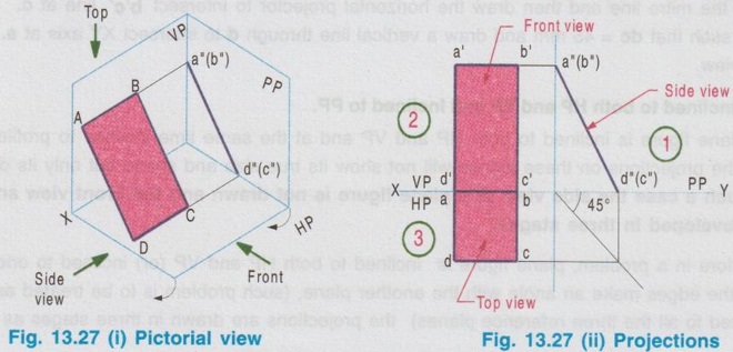
Stage I: (First Position)
Stage II: (Second Position)
Stage III: (Third Position (or) Final Position)
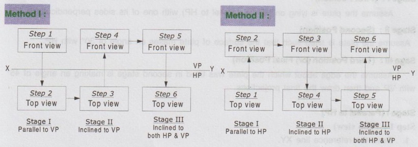
Stage I (Parallel to HP)
Stage II (Surface Inclined to HP)
Stage III: (Final position)
Stage I: (Parallel to HP and Perpendicular to VP)
Stage II (Inclined to HP and Perpendicular to VP)
Stage III (Inclined to HP and Inclined to VP)
Stage I: (Parallel to VP and Perpendicular to HP)
Stage II (Inclined to VP and Perpendicular to HP)
Stage III (Surface inclined to VP and an edge inclined to HP)
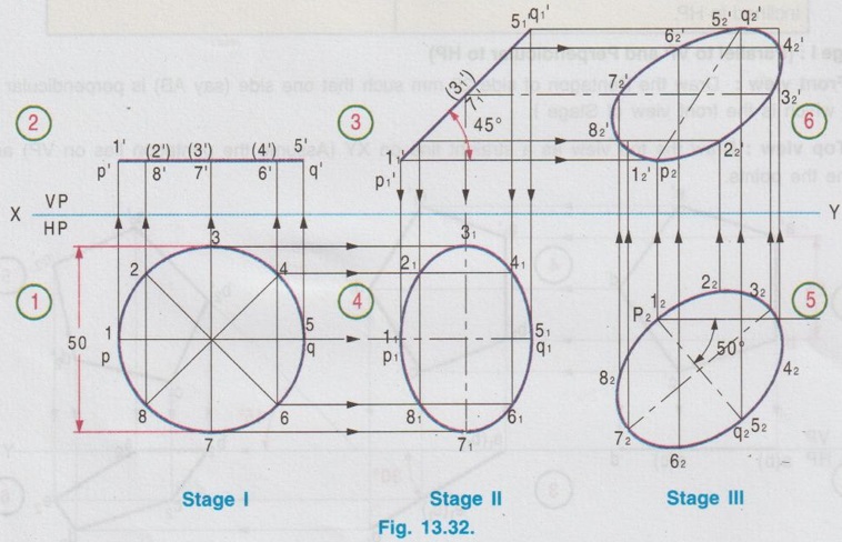
Stage I (Circular lamina parallel to HP & Perpendicular to VP)
Stage II (Circular lamina inclined to HP and Perpendicular to VP)
Stage III (Lamina inclined to HP and diameter inclined to VP)
Stage I (Parallel to HP & Perpendicular to VP)
Stage I (Parallel to VP & Perpendicular to HP)
Stage II (Inclined to VP and Perpendicular to HP)

Engineering Graphics: Unit II (d): Projections of Planes : Tag: : Engineering Graphics (EG) - Projections of planes inclined to Both HP & VP
Related Topics
Related Subjects

Engineering Graphics
GE3251 eg 2nd semester | 2021 Regulation | 2nd Semester Common to all Dept 2021 Regulation