Engineering Graphics: Unit II (d): Projections of Planes
Position of Plane Surface
Engineering Graphics (EG)
A plane surface may occupy any one of the positions described below in first quadrant angle with respect to HP & VP.
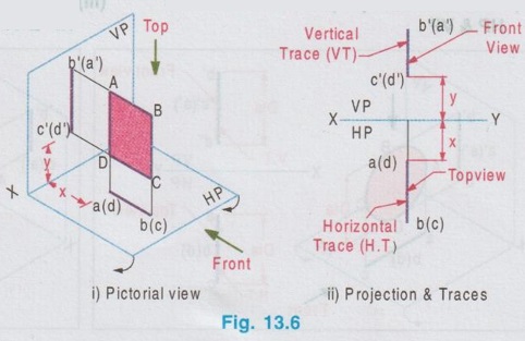
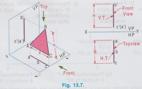
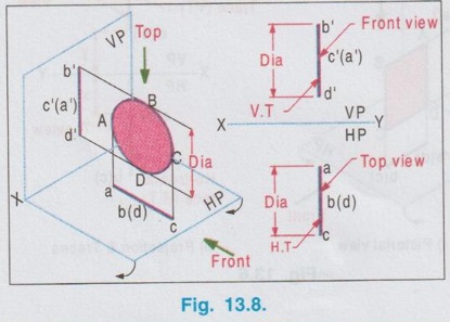
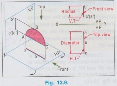
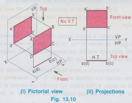
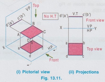
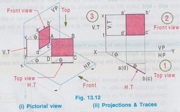
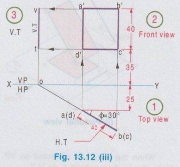
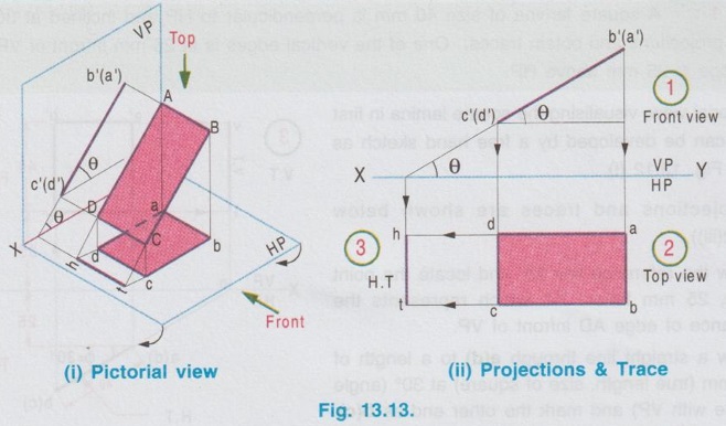
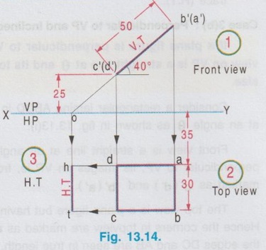
POSITION OF PLANE SURFACE A plane surface may occupy any one of the positions described below in first quadrant angle with respect to HP & VP. Projections of plane figures, placed in first quadrant for the above cases are described below. Case 1: Perpendicular to both the planes If a plane figure is perpendicular to both the reference planes its projections on both the reference planes will be straight lines perpendicular to the reference line XY. Consider a square of side `a' kept in first quadrant, perpendicular to both HP and VP, x distance in front of VP and height h above HP as shown in Fig. 13.6(i). The front view is a straight line. The corners B and C are visible where as the corners A and B, which are on the backside are hidden. Hence these corners are noted as b' (a') and c' (d') respectively. Since the lamina is perpendicular to VP, the front view b' (a')- c' (d') is perpendicular to the reference line XY. The point c'(d') is marked y distance above XY which represents the height of lamina above HP. Similarly when the lamina is observed for its top view from the direction shown in figure, the top view is a straight line. The corners A and B are visible from the direction shown where as the corners D and C are hidden. Hence the end points in top view are marked as a(d) and b(c) respectively. Since the lamina is perpendicular to HP, the top view is perpendicular to the reference line XY, being the point a(d) at x distance below XY which represents the distance of lamina infront is the distance of VP. Traces: The lamina is projected towards the reference planes to intersect with the planes. Clearly V.T and H.T are the straight lines which coincides with front view and top view respectively. To understand the projection of plane surfaces kept perpendicular to both the reference planes, some of the simple plane figures are taken and the final projection are presented below: (i) Triangular lamina perpendicular to both HP & VP (ii) Circular lamina perpendicular to both HP & VP (iii) Semi circular lamina perpendicular to both HP & VP Case 2(a): Perpendicular to HP and Parallel to VP If a plane figure is perpendicular to HP and parallel to VP, its projection on HP ie, top view is a straight line and the projection on VP, ie, front view is the same plane figure having true shape and size. Consider a rectangle ABCD in first quadrant, perpendicular to HP and parallel to VP as shown in Fig. 13.10(i). Front view: Since the plane figure is parallel to VP, its projection on VP is the same plane figure having true shape and size. corners are marked as a', b', c' and d' Distance of the edge d' c' above XY is the height of the bottom edge of rectangle above HP. Top view: Since the plane figure is perpendicular to HP, its projection on HP is a straight line. When the object is viewed from top, the corner A is visible, but the corner D is on the rear side of A and on the same line. Hence the corner is marked as a(d). Similarly the other end of the line is marked as b(c). Distance of the line a(d) - b(c) below XY is the distance of rectangle in front of VP. Traces: If projected the object will not meet VP since the object is parallel to VP. Hence No V.T. But if projected the object will meet HP at a straight line, which is the top view of rectangle. Hence the topview itself is H.T. Case 2(b): Perpendicular to VP and Parallel to HP If a plane figure is perpendicular to VP and parallel to HP, its projection on VP ie, front view is a straightline and the projection on HP, ie, topview is the same plane figure having true shape and size. 1. Consider a square lamina ABCD in first quadrant, parallel to HP and perpendicular to VP as shown in Fig. 13.11(i). 2. Since the lamina is parallel to HP, Top view is the same plane figure having true shape and size. No horizontal trace (H.T). 3. Since the lamina is perpendicular to VP, front view is a straight line, parallel to XY. Front view itself is its vertical trace. Projections and traces of the square lamina are shown in Fig. 13.11(ii). Note: This case is just inverse of the previous case 2a, perpendicular to HP and Parallel to VP. Front view and top view can be interchanged. Case 3(a): Perpendicular to HP and Inclined to VP. If a plane figure is perpendicular to HP and inclined to VP at angle, then its top view on HP is a straight line at and its front view on VP is a plane figure of reduced shape and size. Consider a square lamina ABCD in first Quadrant, perpendicular to HP and inclined to VP at an angle as shown in Fig. 13.12(i). The top view is a straight line at an angle with XY line. Since the edges AB and DC are perpendicular to HP, image of the edge AB on HP, ie, top view will show the true length of edge AB. Front view is a plane figure but having reduced shape and size. All the edges are visible hence the corners are marked as a' b' c' d'. It is to be noted that, though the lamina is inclined to VP at an angle ϕ, the edges AD and BC are parallel to VP. Hence in front view the edges a'd' and b' c' shows the true length but the edges a' b' and d' c' are fore-shortened. When the lamina is projected on HP for its horizontal trace, it will intersect HP at a straight line a(d) b(c). Hence the top view itself is its H.T. When the lamina is projected on VP for its vertical trace, it will intersect VP at a straight line as shown in fig. 13.12(i), known as the vertical trace (V.T). The projections and traces are shown in Fig. 13.12(ii). Note: 1) Since the true length and true angle can be shown in top view, draw top view first and from the top view project for front view. 2) Finally draw the traces by projecting Front view and Top view as shown in Fig. 13.12(ii). Example 1: A square lamina of size 40 mm is perpendicular to HP and inclined at 30° to VP. Draw the projections and obtain traces. One of the vertical edges is at 25 mm infront of VP and the bottom edge is 35 mm above HP. Pictorial view, visualising the square lamina in first quadrant can be developed by a free hand sketch as shown in Fig. 13.12 (i). Final projections and traces are shown below (Fig. 13.12(iii)). 1. Draw the reference line XY and locate the point a(d), 25 mm below XY which represents the distance of edge AD infront of VP. 2. Draw a straight line through a(d) to a length of 40 mm (true length, size of square) at 30° (angle made with VP) and mark the other end as b(c). 3. Draw the vertical projectors through the end points of top view. 4. Locate the point d' on projector drawn through a(d), 35 mm above XY which represents the height of bottom edge above HP. 5. Draw the horizontal line through d', to intersect the projector drawn through b(c) at c'. 6. Mark the point a' such that d' a' = 40 mm, true length, ie., side of square. 7. Draw horizontal line through a' to intersect the projector drawn through b(c) at b'. 8. Project the top view to intersect the reference axis at O and then draw vertical projector through O. 9. Draw the horizontal projectors through the points a' and d' to intersect the vertical projector drawn through O at v and t. 10. Now the line v-t is the vertical trace (V.T) and the top view a(d)-b(c) itself is the Horizontal trace (H.T). Case 3(b): Perpendicular to VP and Inclined to HP If a plane figure is perpendicular to VP and inclined to HP at an angle θ, then its front view on VP is a straight line at θ and its topview on HP is a plane figure of reduced shape and size. Consider a rectangular lamina ABCD in first quadrant, perpendicular to VP and inclined to HP at an angle θ as shown in fig. 13.13(i). to('s) 'd-(b)'s sm Front view is a straight line at an angle θ with XY line. Since the edges AD and CB are perpendicular to VP, its images on VP ie, front view is a straight line showing the true length and marked as c'(d') and b' (a'). The top view is a plane figure but having reduced shape and size. All the corners are visible. Hence the corners in topview are marked as a b c d. Edges DC and AB are parallel to HP. Hence the edges DC and AB are seen in true length. Since the edges DA and CB are inclined to HP, these are fore-shortened in top view. When the lamina is projected on VP, it will intersect VP at a straight line c'(d') - b' (a'). Hence the front view itself is its V.T. When the lamina is projected on HP, it will intersect HP at a straightline as shown in Fig. 13.13(i) known as the horizontal trace (H.T), marked as h-t. The projections and traces are shown in Fig. 13.13(ii). Note: 1. Since the true length and true angle can be shown in front view, draw front view first and then from the front view project for top view. 2. Finally draw H.T by projecting top view and front view as shown in Fig. 13.13 (ii). Example 2: A rectangular lamina of 50 mm × 30 mm is perpendicular to VP and inclined at 40° to HP. Draw the projections and obtain traces. Front edge is at 35 mm infront of VP and the bottom edge is 25 mm above HP. Pictorial view, visualising the rectangular lamina in first quadrant can be developed by a free hand sketch as shown in Fig. 13.13(i). Final projections and traces are shown in Fig. 13.14. 1. Draw the reference line XY and locate the point c' (d'), 25 mm above XY. 2. Draw the line c'(d') - b' (a') of 50 mm length at 91s an angle of 40° with XY which is the front view bns and draw the vertical projectors through the points c' (d') and b' (a'). 3. Locate the point d at 35 mm below XY and draw the horizontal line through the point d to intersect the projector drawn through b' (a') at a. 4. Measure dc = 30 mm and draw the horizontal line through c to intersect the projector drawn through a at b. dabc is the top view. 5. Project the front view to intersect the reference line at O and draw a vertical projector through O. 6. Draw horizontal projectors through the points d and c to intersect the projector drawn through O at h and t. The line h-t represents the horizontal trace (H.T) and the front view c' (d')- b' (a') itself is the vertical trace (V.T). 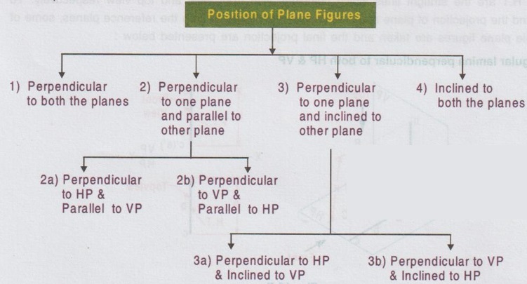
Engineering Graphics: Unit II (d): Projections of Planes : Tag: : Engineering Graphics (EG) - Position of Plane Surface
Related Topics
Related Subjects

Engineering Graphics
GE3251 eg 2nd semester | 2021 Regulation | 2nd Semester Common to all Dept 2021 Regulation