Engineering Graphics: Unit III (b): Projections of Solids
Naming the Corners of the Solids
Projections of Solids | Engineering Graphics (EG)
It is desired to name the corners and axis systematically so that the projections can be read and understood easily.
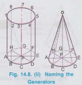
NAMING THE CORNERS OF THE SOLIDS It is desired to name the corners and axis systematically so that the projections can be read and understood easily. Hence in this chapter, the first set of names for corners (say the corners at the base) are marked as A, B, C, D etc., whereas the second set of names for corners (say the corners at the top base) are marked as 1, 2, 3, 4, etc., the axis of solid is named as O-P. The way of naming the corners of some of the Right regular A solids are shown in fig. 14.8(i) and 14.8(ii).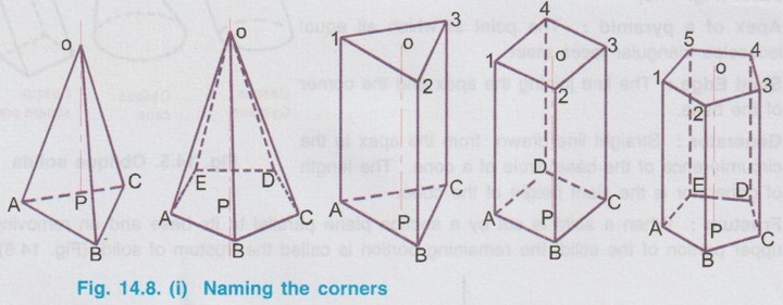
Engineering Graphics: Unit III (b): Projections of Solids : Tag: : Projections of Solids | Engineering Graphics (EG) - Naming the Corners of the Solids
Related Topics
Related Subjects

Engineering Graphics
GE3251 eg 2nd semester | 2021 Regulation | 2nd Semester Common to all Dept 2021 Regulation