Engineering Graphics: Unit 0 (c): Lines, Lettering and Dimensioning
Method of Dimensioning Some Common Features
Engineering Graphics (EG)
Circles : A circle may be dimensioned by its diameter represented by the symbol ϕ or by its Radius represented by the letter R.
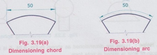
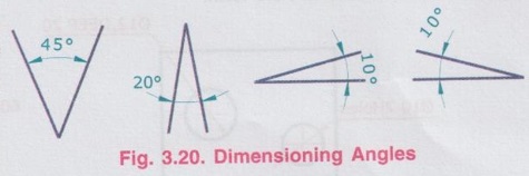
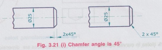
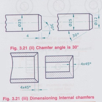
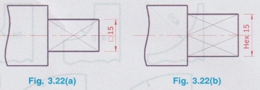
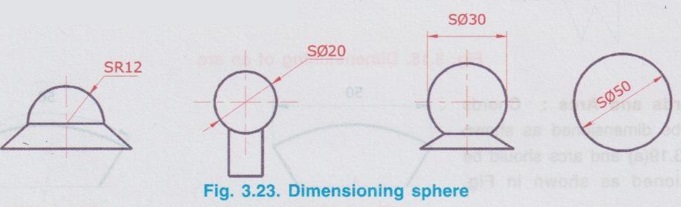
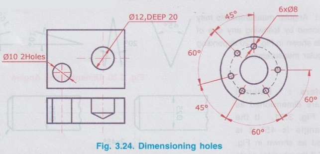
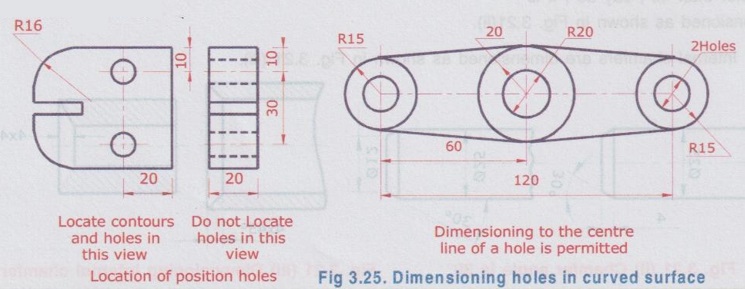
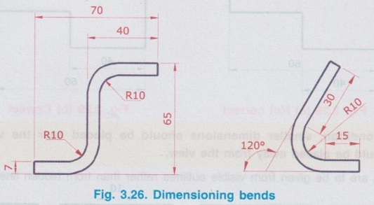
METHOD OF DIMENSIONING SOME COMMON FEATURES 1. Circles : A circle may be dimensioned by its diameter represented by the symbol ϕ or by its Radius represented by the letter R. A circle may be dimensioned by any one of the ways shown in Fig. 3.17, depending on the diameter (size) of circle. 2. Radius : Radius of an arc may be dimensioned by its radius represented by the letter R by any one of the ways shown in Fig. 3.18. Note that only one arrow head termination is used and it may be located depending upon the feature. As far as possible, the dimension line of a radius should pass through the centre of the arc. The various methods of dimensioning of an arc are shown in Fig. 3.18. 3. Chords and Arcs : Chords should be dimensioned as shown in Fig. 3.19(a) and arcs should be dimensioned as shown in Fig. 3.19(b). 4. Angles : Angular measurements may be dimensioned by following any one of the methods shown in Fig. 3.20 depending on the angular measurement. 5. Chamfers : External chamfers are dimensioned as shown in Fig. 3.21. If the chamfer angle is 45° it is dimensioned as shown in Fig. 3.21(i) and if the chamfer angle is other than 45°, say 30°, it is dimensioned as shown in Fig. 3.21(ii). Internal chamfers are dimensioned as shown in Fig. 3.21 (iii). 6. Squares and Hexagons : A square should be dimensioned by preceding with the symbol pppp and a hexagon should be dimensioned by preceding with the word HEX as shown in Fig. 3.22(a) and (b) respectively. 7. Spheres : A sphere may be dimensioned by its diameter represented by the symbol Sϕ or by its radius represented by the letter SR, where S stands for sphere. A sphere may be dimensioned by any one of the ways shown in Fig. 3.23. 8. Holes : Holes are dimensioned as shown in Fig. 3.24. It is marked by their centre line and the depth of hole is stated in note form. 9. Holes in curved surface : Holes on curved surfaces are dimensioned by using angular dimensions as shown in Fig. 3.25. 10. Bends : Bends are dimensioned as shown in Fig. 3.26. below.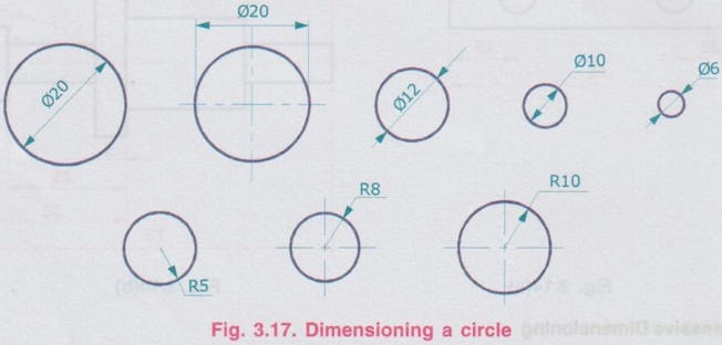

Engineering Graphics: Unit 0 (c): Lines, Lettering and Dimensioning : Tag: : Engineering Graphics (EG) - Method of Dimensioning Some Common Features
Related Topics
Related Subjects

Engineering Graphics
GE3251 eg 2nd semester | 2021 Regulation | 2nd Semester Common to all Dept 2021 Regulation