Engineering Graphics: Unit II (a): Orthographic Projection
Important Hints
Orthographic Projection | Engineering Graphics (EG)
1. A cylinder placed vertically is seen as a circle in top view and as a rectangle in front view of width equal to the diameter of the cylinder.
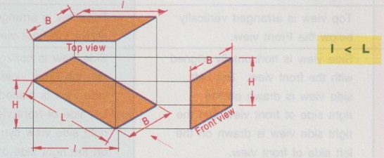
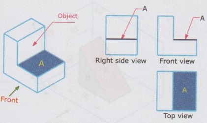
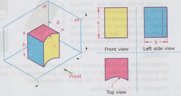
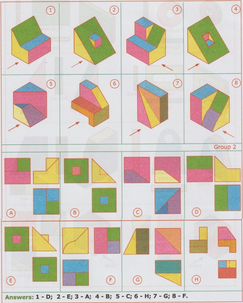
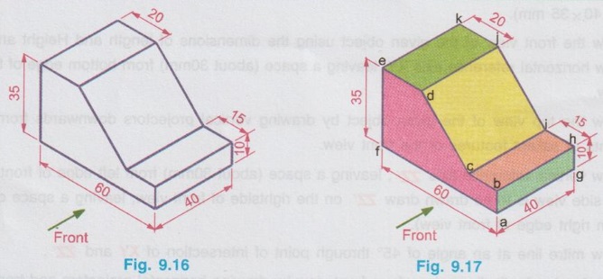
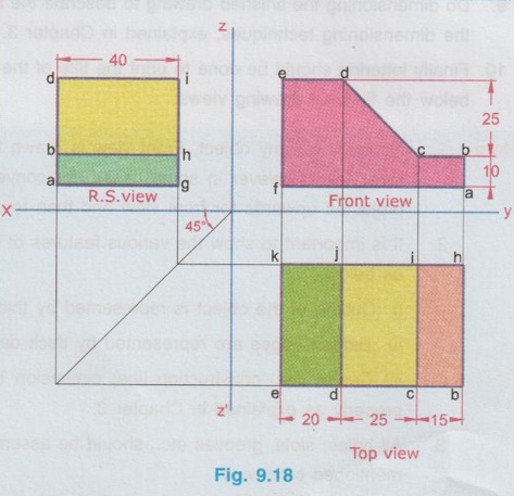
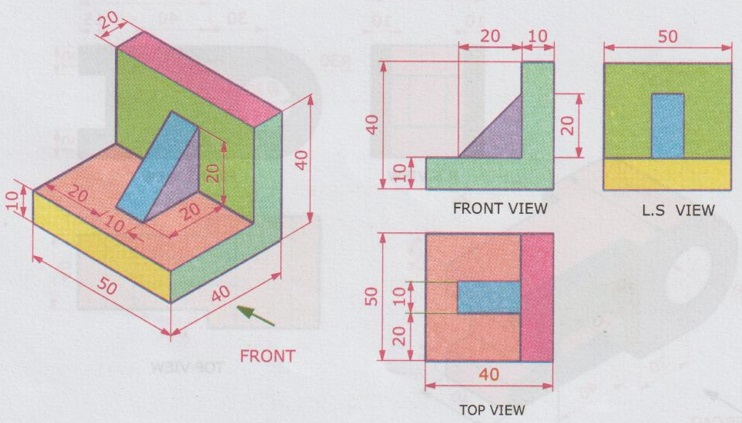
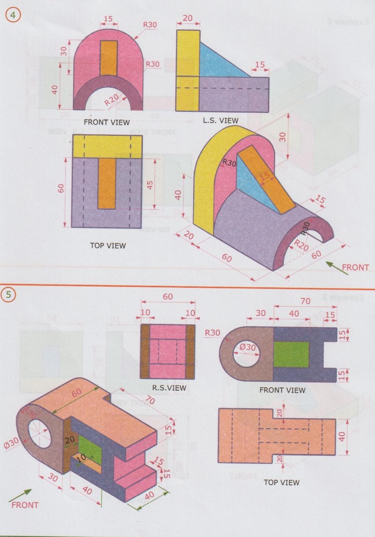
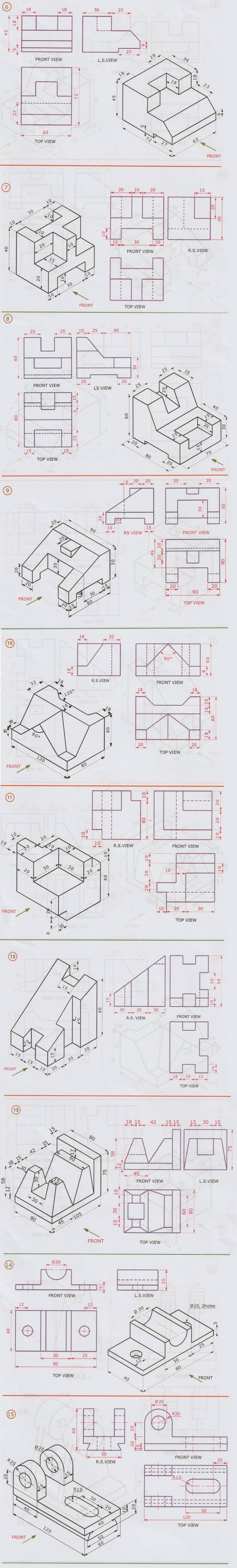
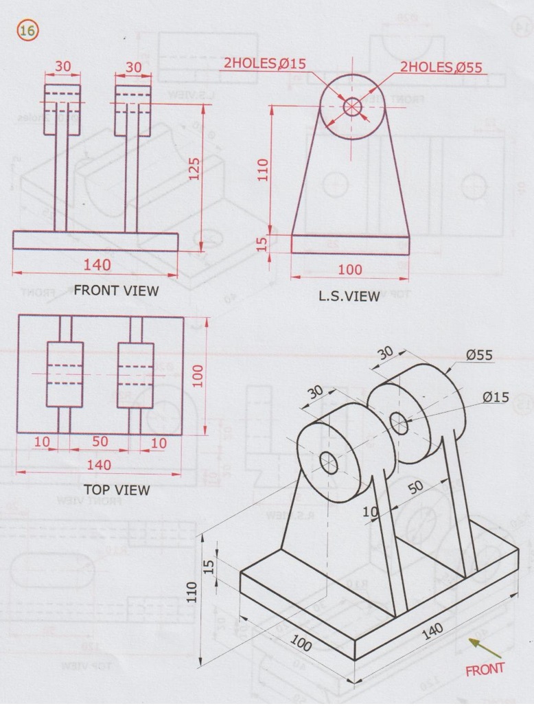
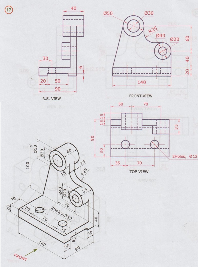
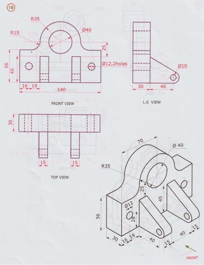
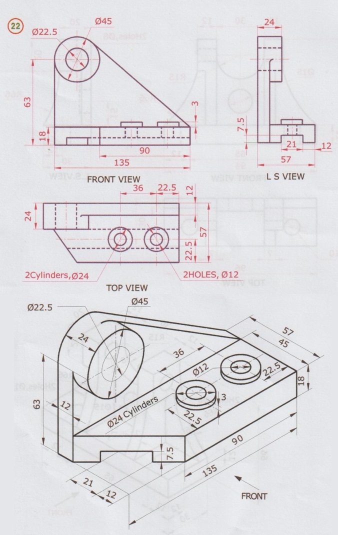
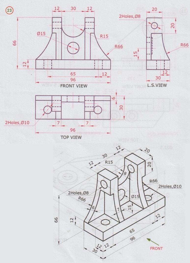
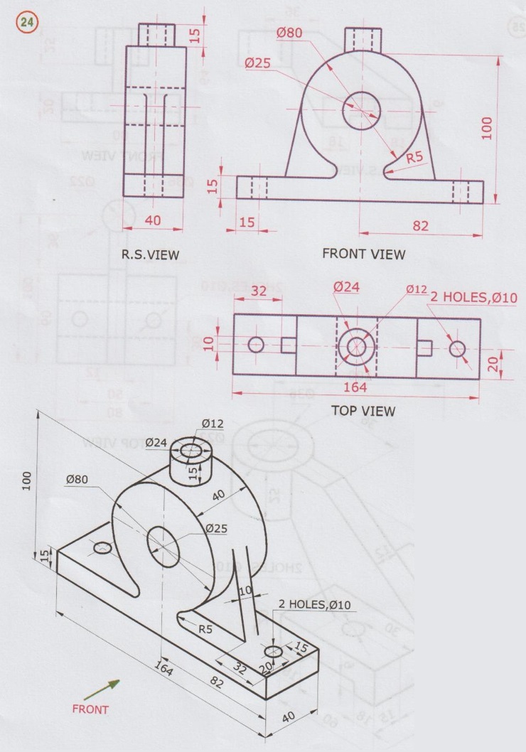
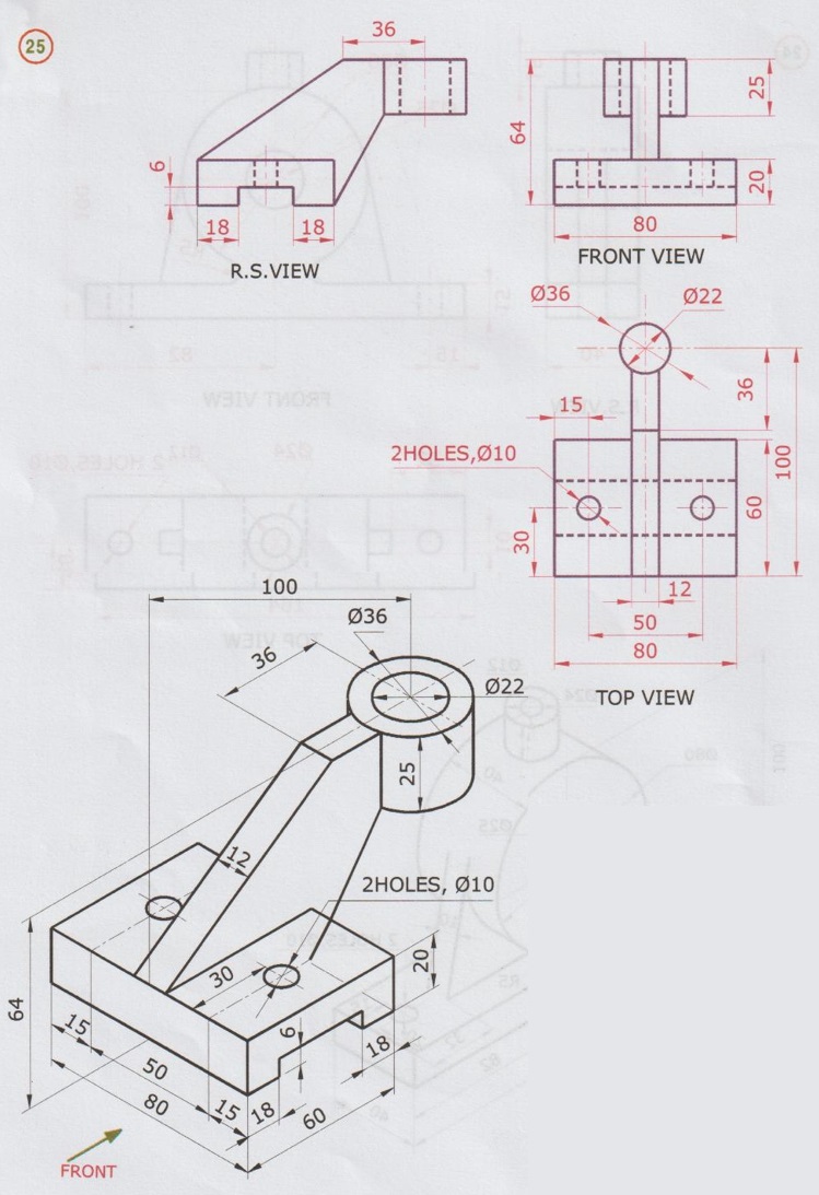
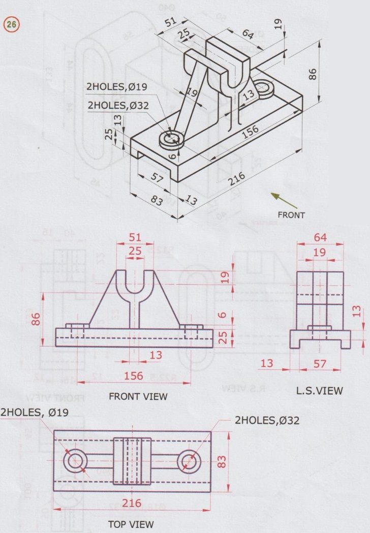
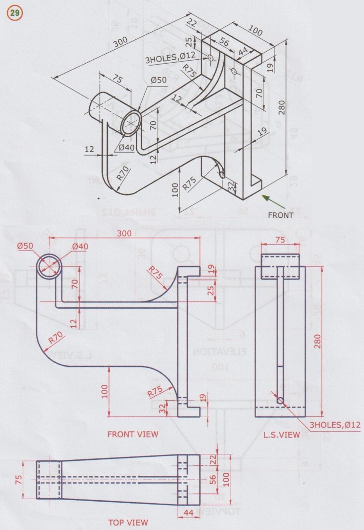
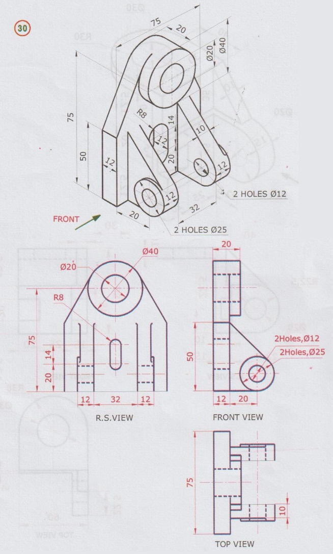
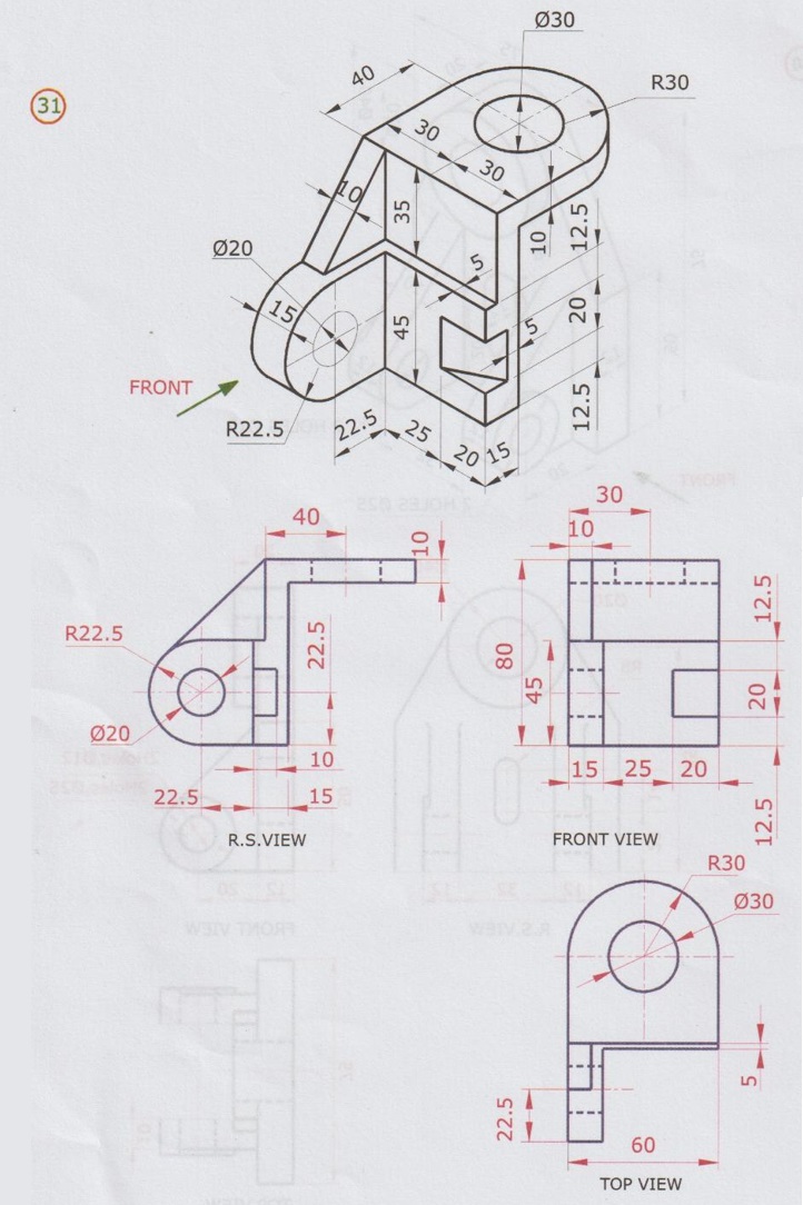
IMPORTANT HINTS 1. A cylinder placed vertically is seen as a circle in top view and as a rectangle in front view of width equal to the diameter of the cylinder. 2. Projections and cut-holes placed infront are seen similar in front view. But in top view (and side view) the cut-holes are represented by dotted line as below. 3. A tapered surface will be seen as a rectangle. 4. A curved horizontal surface will be seen as straight in top view. If a surface of an object is parallel to one of the reference planes of projection, the projection of the surface on that plane will have its true shape and size, where as the projection of a surface which is normal to the plane of projection is represented by a straight line. In fig shown above the surface A is parallel to HP. Hence the true shape and size of the surface A is shown in the view projected on HP. (ie., Topview). But the surface A is perpendicular to VP and PP, hence it is shown as a straight line in Front view and Right hand side view. If a surface of an object is perpendicular to one of the reference planes and inclined to the other two Principal planes, the projections of the surface to which it is perpendicular will be a straight line, inclined to the other two reference planes. But the projections of the surface on the reference plane to which it is inclined will appear fore- shortened. In figure shown above, the surface B is inclined to VP and HP but perpendicular to PP. Hence the projection of surface on PP is a straight line inclined to VP and HP. But the projection of the surface B on VP and HP will appear fore-shortened. If a surface of an object is inclined to all the three reference planes (called as oblique surface) its projections on reference planes (HP, VP and PP) will show areas which does not give the true shape and size of the surface. In fig. shown below, the surface 'C' is inclined to all the reference planes VP, HP and PP. Hence its projections on the reference planes will not give true shape and size of the surface. 8. Surface inclined to the plane of projection will appear foreshortened in that plane. Note: since the surface is parallel to VP, Front view (Surface B) will show the true shape and size of the object, whereas the surface A is fore-shortened in Top view and L.S. view since the surface A is inclined to HP and PP. 9. Surface curved to the plane of projection will appear as a rectangle in that plane as shown in figure. 10. Orthographic projections of some of cone the simple objects are given below for ready reference and clear understanding. Note: 1. All the views are in First angle projection. 2. Arrow ( 3. L.S View - Left side view ; R.S View - Right side view Identifications of Object Surfaces in Orthographic Views (The direction of Arrow Mark is for Front view) Match the objects shown in Group 1 with their respective orthographic views as given in Group 2 Group 1 Example 1: The pictorial view of an object is shown in Fig. 9.16. Draw (i) Front view in the direction of arrow mark (ii) Top view and Left side view (All dimensions are in mm). Note: 1. For better understanding various shades are used in the object and the corresponding surfaces in orthographic projections. But it is not advised to use any colour pencil in examination. 2. Similarly for clear understanding at this initial level the various corners in the object are named by the letters a, b, c etc. as shown in Fig. 9.17 below and the corresponding corners are marked in the orthographic projections. But examination point of view, the corners need not be identified. 3. Few examples presented below are used with various shades to help the students to identify the surfaces of objects in orthographic projections. 4. Mitre line is used to draw side view. But it is general practice that the mitre line is not shown in multiview orthographic projection. The orthographic projections of the object shown in Fig. 9.16 for the direction of front view shown by arrow mark are presented (In First angle Projection) in Fig. 9.18. 1. At first, over all dimensions of the given object to be determined to decide the required space for all the three views. For the given object, over all dimensions are: Length = 60 mm, Breadth = 40 mm and Height 35 mm. 2. Allocate sufficient space for front view (Rectangle, length × height ie., 60 × 35 mm); Top view (Rectangle, length × breadth ie., 60 × 40 mm) and Right side view (Rectangle, breadth × height ie., 40 × 35 mm). 3. Draw the front view of the given object using the dimensions of length and Height and then draw horizontal reference axis XY, leaving a space (about 30mm) from bottom edge of the front view. 4. Draw the top view of the given object by drawing vertical projectors downwards from all the points of salient features of the front view. 5. Draw vertical reference axis ZZ', leaving a space (about 30mm) from left edge of front view (If left side view is to be drawn draw ZZ' on the rightside of front view, leaving a space of 30mm from right edge of front view). 6. Draw mitre line at an angle of 45° through point of intersection of XY and ZZ'. 7. Transfer the depth dimensions from front view by drawing horizontal projectors and transfer the breadth dimensions from top view by drawing horizontal projectors to intersect mitre line and then vertical projectors through these intercepting points as shown in Fig. 9.18. 8. After completing the required views, rub off all unnecessary lines except the centre lines and darken the outlines of the object to give good appearance. 9. Do dimensioning the finished drawing to describe the shape and size of the object according to the dimensioning techniques, explained in Chapter 3. 10. Finally lettering should be done to print the title of the drawing and the names of various views below the finished drawing views. Note: 1. Normally for any object, Front view is drawn first then it is projected for top view and side view. However in some cases, for convenience top view is drawn first then it is projected upwards for front view and then transfered to side view. 2. It is important to show the various features of object by suitable line type and thickness as below. i) Outline of the object is represented by thick continuous line type using HB pencil. ii) Hidden edges are represented by thick dashed line. iii) Centre line, construction line, dimension line and extension line should be drawn properly as explained in Chapter 3. 3. All holes, slots, grooves etc., should be assumed to run right through the object unless mentioned otherwise. 4. If radius of any curved portion is not specified, it may be assumed suitably. 5. If direction for front view is not given it may be assumed such that the direction which shows the longest face of the object or the most informative features. Example 2 Example 3


5. Projection of parallel surface
6. Projection of Inclined surface

7. Projection of Oblique Surface


![]() ) indicates the direction for Front view.
) indicates the direction for Front view.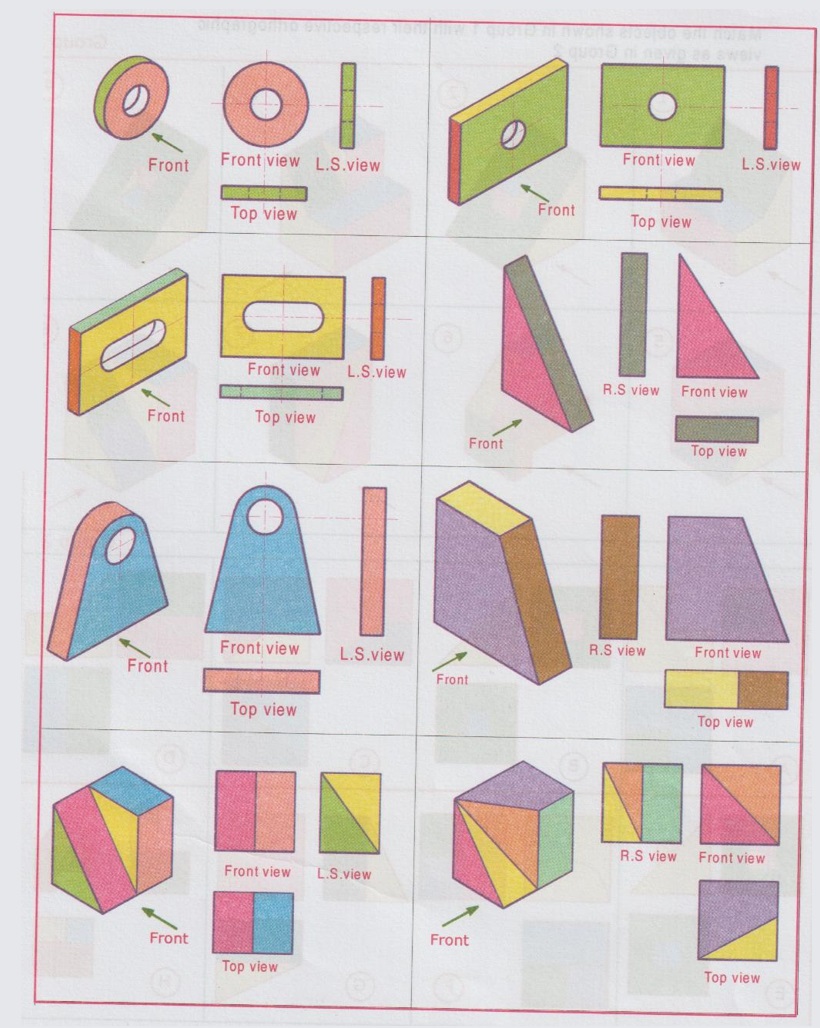


Engineering Graphics: Unit II (a): Orthographic Projection : Tag: : Orthographic Projection | Engineering Graphics (EG) - Important Hints
Related Topics
Related Subjects

Engineering Graphics
GE3251 eg 2nd semester | 2021 Regulation | 2nd Semester Common to all Dept 2021 Regulation