Engineering Graphics: Unit II (a): Orthographic Projection
Construction of Three Views with the help of Mitre Line
Orthographic Projection | Engineering Graphics (EG)
Both the dimensions width and height on the side view are NOT marked by scale.
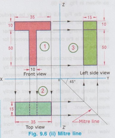
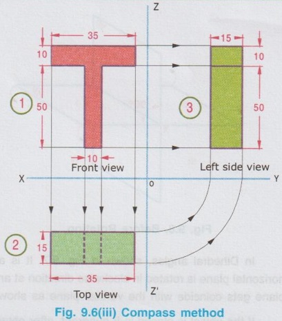
CONSTRUCTION OF THREE VIEWS WITH THE HELP OF MITRE LINE Pictorial view of an object is shown below in Fig. 9.6(i). For the position of observer shown in Fig. 9.6 (i), the Front view, Top view and the left hand side view are already shown in Fig. 9.5 (ii). The construction of these views are explained below. 1. Draw XY axis. 2. Draw ZZ' axis to intersect the axis XY at O, and perpendicular to XY axis. 3. Draw the front view as shown in fig. Ensure that some minimum space is maintained between bottom edge of front view and XY axis & right edge of front view and OZ axis, for dimensioning and writing foot note. 4. Draw vertical projectors from all the corners of the front view downwards and draw the top view, below XY axis, by leaving some minimum space between upper edge of top view and XY axis. Note: Both the dimensions, length and height are marked by using scale on front view, where as only one dimension, width is marked by using scale on top view, and the length of object in top view is simply projected down from the front view. 5. Draw Mitre line' at an angle of 45° from XY axis anto as shown in fig. (If right side view is required, draw ZZ' axis and mitre line on the left side of top view). 6. Draw horizontal projectors from all the corners of top view to intersect the mitre line and through these points of intersection, draw vertical upward projectors. 7. Draw Horizontal projectors from all the corners of the front view to intersect the vertical projectors, drawn from mitre line. 8. Join the corresponding points and complete the left side view as shown in fig. Note: Both the dimensions width and height on the side view are NOT marked by scale. They are directly projected from the other two views, Front view and Top view. Height is projected from the front view and the width is projected from the top view. To draw the side view an another method called "Compass method" is also followed as detailed below. Draw the front view and topview as explained in Mitre line method. (upto the step 4) i) Draw the horizontal projectors from all the corners of top view to intersect the OZ' axis and note the points of intersection. ii) With 'O' as centre and radius equal to the corresponding distances of points of intersection measured from O, draw arcs to cut OY axis and note down the points of intersection. iii) Draw the vertical projectors through these points of intersection to meet the horizontal projectors drawn from all the corners of the front view. iv) Join the corresponding points and complete the left side view as shown above. Note: If Right hand side view is required, draw OZ axis on the left side of front view and follow the same procedure explained above.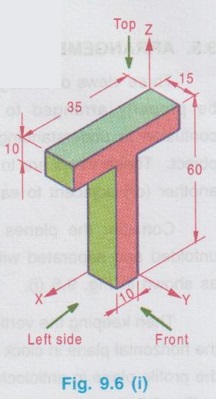
Aliter to draw side view by compass method
To Draw side view :
Engineering Graphics: Unit II (a): Orthographic Projection : Tag: : Orthographic Projection | Engineering Graphics (EG) - Construction of Three Views with the help of Mitre Line
Related Topics
Related Subjects

Engineering Graphics
GE3251 eg 2nd semester | 2021 Regulation | 2nd Semester Common to all Dept 2021 Regulation