Basic Electrical and Electronics Engineering: Unit II: Electrical Machines
Construction, Operation Working Principle of D.C generator
D.C generator is a machine which converts mechanical energy in to electrical energy. Direct -current generators are used to supply power for radio equipment, battery charging, electrolytic cells etc.
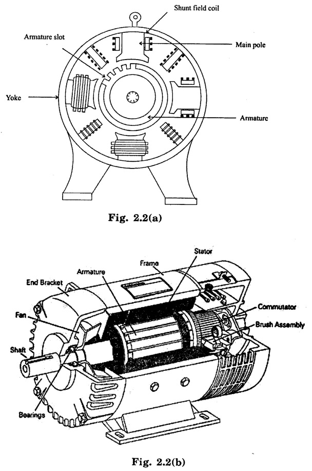
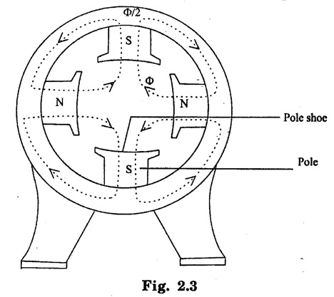
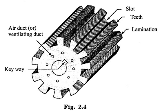
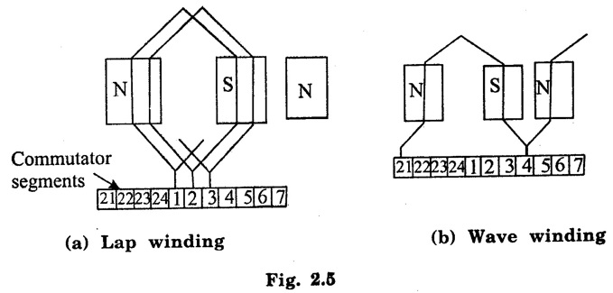
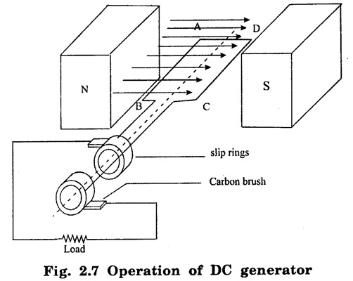
D.C GENERATOR D.C generator is a machine which converts mechanical energy in to electrical energy. Direct -current generators are used to supply power for radio equipment, battery charging, electrolytic cells etc. A disadvantage common to all d.c machines is the complexity of design, mainly due to the usage of brush gear. This brush gear can also cause sparking. D.C generators and D.C. motors have same general construction. A d.c machine consists of two main parts: (i) stationary part, called the field structure, it is mainly used for producing magnetic flux. (ii) a rotating part called, the armature, where mechanical energy is converted into electrical energy (generator), or electrical energy is converted into mechanical energy (motor). The stationary and rotating parts are separated from each other by an air gap. The main parts of a d.c machine (a generator or a motor) are described below. It is the outermost cylindrical part of the machine. The yoke is made up of solid cast iron or cast steel or forged steel. The yoke acts as the protecting cover for the machine and also provides a return path for magnetic flux created by filed windings. In small d.c machines, yoke is made up of cast iron. In large d.c generators, the yoke is made of cast steel from the consideration of better magnetic properties. Poles are also called as field magnets. It consists of pole core, pole shoe and pole coils. Pole core: The pole core are made of cast steel or forged steel. In some machines, pole core are made from laminated sheet steel. Pole cores holds pole coils. Pole shoe: It is the lower portion of the pole. The main function of the pole shoe are (a) it supports the field coil. (b) it spreads out the magnetic flux in the air gap. Since pole shoe is of large cross section, it reduces the reluctance of the magnetic path. The field coils are wound on pole cores. They are connected in series and the connections are so arranged on different poles that when a direct current is passed through this winding, the poles get magnetized to N and S polarities alternatively. Thus filed system is responsible for producing the required working flux in the air gap. The field coils are made from enameled copper wire. The armature is that part of the d.c machine where an e.m.f is induced as it rotates relative to the main field. The armature consists of the toothed core, a winding dropped in the core slots, and a commutator mounted on the armature shaft. Iron material is used for armature core. The rotation of solid iron core in the magnetic field results in eddy currents. The eddy currents flows in the core causes the wastage of energy and heat dissipation problem. To reduce the eddy current loss, the armature core made up of thin silicon - steel laminations. The laminations are usually 0.4 to 0.5mm thick and are insulated with varnish. The armature winding consists of sections or coils. The armature winding is housed in slots on the surface of the armature. The conductors of each winding/coil are so spaced that when one side of the coil is under a north pole, the opposite side is under a south pole. Depending upon the manner in which the armature conductors are connected to the commutator degments, there are two types of armature windings in d.c. machine: a) Lap winding: Lap winding is suitable for low voltage, high current generators. Normally it is used for generators of capacity more than 500A. In lap winding, number of parallel paths equal to number of poles in the machine (A=P). Also, number of brush sets required is equal to number of poles. b) Wave winding: Wave winding is suitable for high voltage, low current generators. It is mainly preferred for generators of capacity less than 500 A. In wave winding number of parallel paths A=2. Also number of brush required is always equal to 2. The commutator, which is a typical component of d.c machines. It is shown in figure 2.6. It is used to collect the current from armature conductor. The commutator is a hollow cylindrical structure and made up of wedge shaped segments of high conductivity hard drawn copper. The segments are insulated from each other by thin layer of mica. The function of the commutator is to convert the e.m.f induced in the armature conductors in to unidirectional voltage across the load impedance. The function of the brush is to collect current from the rotating commutator and deliver it to the external load impedance. The brushes are made of carbon. The brushes are mounted in a box type of brush holder and are held on the commutator by a spring. Bearings are used to help the rotor shaft to rotate smoothly. Ball bearings or roller bearing are preferably used. For small machine, ball bearing is used and for heavy a) Lap winding: Lap winding is suitable for low voltage, high current generators. Normally it is used for generators of capacity more than 500A. In lap winding, number of parallel paths equal to number of poles in the machine (A=P). Also, number of brush sets required is equal to number of poles. b) Wave winding: Wave winding is suitable for high voltage, low current generators. It is mainly preferred for generators of capacity less than 500 A. In wave winding number of parallel paths A=2. Also number of brush required is always equal to 2. Consider a single turn loop ABCD is rotating clockwise direction in a uniform magnetic field with a constant speed. As the loop rotates, the flux linking the coils sides AB and CD changes continuously. Therefore emf induced in these coils sides also changes but the emf in one coil side adds with that induced in other. If a load is connected across the ends of the loop, then alternating current will flow through the load. The alternating voltage generated in the loop is converted into direct voltage by a device known as commutator.1. Construction of D.C Generator
1) Yoke
2) Poles
3) Field coils
4) Armature
 5) Commutator
6) Brushes
7) Bearings
Basic Electrical and Electronics Engineering: Unit II: Electrical Machines : Tag: : - Construction, Operation Working Principle of D.C generator
Related Topics
Related Subjects

Basic Electrical and Electronics Engineering
BE3251 2nd semester Mechanical Dept | 2021 Regulation | 2nd Semester Mechanical Dept 2021 Regulation

Basic Electrical and Electronics Engineering
BE3251 2nd Semester CSE Dept 2021 | Regulation | 2nd Semester CSE Dept 2021 Regulation