Engineering Graphics: Unit II (d): Projections of Planes
Change of Position Method
Projections of Planes | Engineering Graphics (EG)
Projections for plane figures, perpendicular to one plane and inclined to other plane drawn in previous examples can be drawn only for simple position of plane figures like square, rectangle etc.,
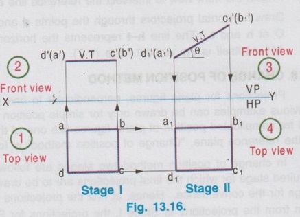
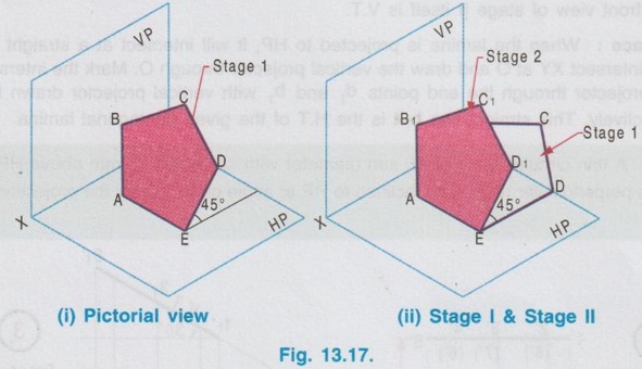
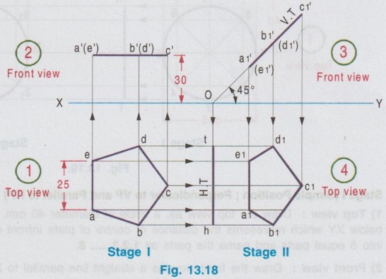
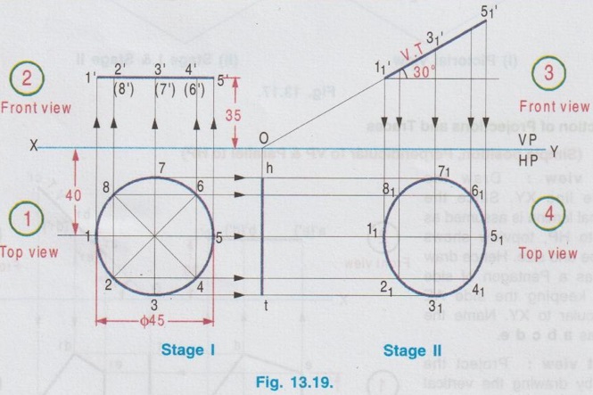
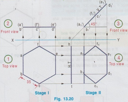
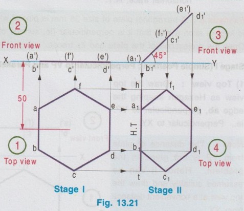
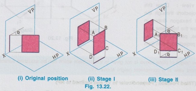
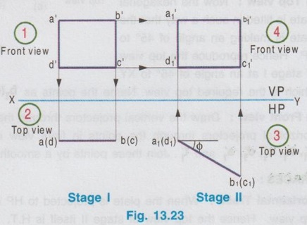
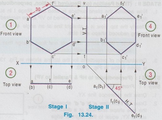
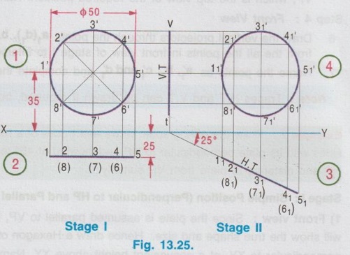
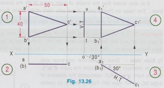
CHANGE OF POSITION METHOD Projections for plane figures, perpendicular to one plane and inclined to other plane drawn in previous examples can be drawn only for simple position of plane figures like square, rectangle etc., But for complicated position of plane figures like one of the edges / corners is specified with respect to the reference plane, "Change of position method" is followed. In change of position method two stages are followed, Stage I and Stage II. Stage II is the required stage for which the final projections are to be drawn, whereas Stage I is the initially assumed stage for the convenience. Hence, at first the projections are drawn for stage I (Simple position) and then from the projections of Stage I, the projections for Stage II (Required stage) are developed. Case (1) Perpendicular to VP and inclined to HP problems by change of position method Consider a plane surface perpendicular to VP and inclined to HP at θ as shown in Fig. 13.15(i). Clearly the front view of original position is a straight line at angle θ with XY and top view of original position is a plane surface having reduced shape and size (Refer case 3b, Fig. 13.13 (i)). The projections are developed in two stages. Stage I: (Simple Position) 1. Assume that the plane surface is perpendicular to VP and parallel to HP as shown in Fig. 13.15(ii). Clearly the front view is a straight line parallel to XY and top view is the plane surface having true shape and size. Stage II: (Tilted position (or) Required position) 1. Now assume the plane surface is tilted from Stage I, in such a way that the plane surface is again perpendicular to VP but inclined to HP at the required angle θ as shown in Fig. 13.15(iii). 2. Clearly the front view is a straight line at an angle θ with XY and top view is a plane figure having reduced shape and size, which are the required projections of the original pósition. Note: While tilting, all points and lines change their relations with the respect to HP, but do not change relation with respect to VP. Advantage of Change of position method Projections of the lamina shown in Fig. 13.15(i) were already drawn by direct method in Fig. 13.13 (ii). In this case the edges AB and CD are parallel to HP and shows true length, Front view eventhough the plane figure is inclined to HP. Hence it was easy to draw these sides in topview. But in cases where no side of the plane figure is parallel to HP, it is difficult to get the views in direct method as explained in article case 3(b). In such cases, change of position method to be followed. Construction of Projections for the lamina shown in fig. 13.15(i) in change of position method is given below: STAGE I (Simple Position, Perpendicular to VP & Parallel to HP) Step 1: (Top View) 1. Draw the reference line XY. 2. Draw the topview abcd showing the true shape and size at a distance below XY, equal to the distance of edge AB infront of VP. Step 2: (Front view) 3. Draw the vertical projectors through the points abcd. 4. Draw a straight line parallel to XY at a distance above XY, equal to the height of lamina above HP. STAGE II (Tilted Position (or) Required position, Perpendicular to VP & Inclined to HP) Step 3: (Front View) 5. Tilt the front view of Stage I at an angle θ with XY, equal to the angle made by the lamina with HP. 6. Name the ends as d ′1(a ′1) and c ′1(b ′1). Step 4: (Top View) 7. Draw the vertical projectors through the points d ′1(a ′1) and c ′1(b ′1). Draw the horizontal projectors through all the points from top view of stage I to intersect the vertical projectors drawn as above. 8. Mark the points of intersection as a1, b1, c1, and d1 and complete the top view. Example 3 : A pentagonal plate of side 25 mm is above HP, one of its sides perpendicular to VP. Draw the projections if the plate is inclined at 45° to HP. Also draw its traces. The plate is 30 mm above HP. One of the sides (AE) of pentagonal plate is perpendicular to VP and the pentagonal plate is inclined to HP. The pictorial view is presented in Fig. 13.17 (i) and the two stages in change of position method are shown in Fig. 13.17(ii). Construction of Projections and Traces Stage I: (Simple position, Perpendicular to VP & Parallel to HP) 1) Top view: Draw the reference line XY. Since the Pentagonal lamina is assumed as parallel to HP, topview shows true shape and size. Hence draw topview as a Pentagon of side 25 mm, keeping the side AE perpendicular to XY. Name the corners as a b c d e. 2) Front view : Project the topview by drawing the vertical projectors through all the corners above XY. Draw the front view, a straight line, parallel to XY and 30 mm above XY which inc represents the height of the plate above HP. Name the points as a' (e'), b' (d) and c'. Stage II: (Tilted Position, Perpendicular to VP and Inclined to HP) 3) Top view: Tilt the front view obtained in Step 1 about the end a' (e') to the given angle of 45° with XY. From the top view of stage I, it is assumed that the pentagon is tilted to an angle 45° about the edge ae. Name the points as a'1, b'1, etc. 4) Front view: From the top view of stage I, draw the horizontal projectors through the points a, b, c, d and e. Draw the vertical projectors through the points a'1 (e'1), b'1(d'1) and c'1. Mark the intersecting points a1 b1 c1 d1 and e1. and join these points which is the required topview of the given position of pentagonal lamina. TRACES Vertical Trace: When the lamina is projected to VP, it will intersect at a straight line, ie, the front view. Hence front view of stage II itself is V.T. Horizontal Trace: When the lamina is projected to HP, it will intersect at a straight line. Hence extend V.T to intersect XY at O and draw the vertical projector through O. Mark the intersecting points of horizontal projector through the end points d1 and b1 with vertical projector drawn through O at t and h respectively. This straight line h-t is the H.T of the given pentagonal lamina. Example 4: A thin circular plate of 45 mm diameter with its centre 35 mm above HP and 40 mm infront of VP is perpendicular to VP and inclined to HP at angle of 30°. Draw the projections and traces of the plate. Stage I (Simple Position; Perpendicular to VP and Parallel to HP) 1) Top view: Draw the top view as, a circle of diameter 40 mm, keeping the centre point 40 mm below XY which represents the distance of centre of plate infront of VP. Divide the circumference into 8 equal parts and name the parts as 1,2,3,..... 8. 2) Front view: Draw the front view as a straight line parallel to XY at 35 mm above XY which represents the height of circular plate 35 mm above HP, by projecting vertical projectors through the points 1, 2, ..... 8 from top view. Stage II: (Tilted Position; Perpendicular to VP and inclined to HP) 3) Front view: Tilt the front view about the point 1' to an angle of 30° with XY. (ie, reproduce the front view obtained in step 2 at an angle of 30° with XY). Name the points as 1'1, 2'1 etc. 4) Top view: Draw the vertical projectors from Front view of Stage II and horizontal projectors from the top view of Stage I. Mark the intersecting points as 11, 21, 31, ..... 81. Join these points by a smooth curve which is the required top view. TRACES: V.T : The front view of stage II itself is its vertical trace. H.T : Extend the V.T to intersect XY at O and draw a vertical projector through O. Let the horizontal projectors through the end points 31 and 71 from the topview of Stage II to intersect the projector drawn through O at h and t. The line h-t represents the horizontal trace, H.T. Example 5: A hexagonal plate of size 35 mm is placed with a side perpendicular to VP. The plate is kept in such a way that it is perpendicular (ie, surface of plate) to VP and inclined to HP at 45°. Draw the projections of the plate and its traces. Stage I (Simple Position; Perpendicular to VP and Parallel to HP) 1) Top view: Draw the top view as Hexagon keeping the edge ab, perpendicular to VP. ie., Perpendicular to XY. Note : The distance of plate from VP is not given in the problem. Hence it can be assumed suitably and draw the top view at a convenient distance from XY. 2) Front view : Draw the vertical projectors through the corners of hexagon drawn in Step 1. Draw the front view as a straight line, parallel to XY by joining the projectors drawn from top view. Note: The height of plate above is not given in the problem which can be assumed suitably. Hence draw the front view at a convenient height above XY. Stage II: (Tilted Position; Perpendicular to VP and inclined to HP) 3) Front view: Draw the front view by reproducing the front view of Stage I at an angle of 45° to XY. Name the points as a'1, b'1 etc. 4) Top view: Draw the vertical projectors through a'1, b'1 etc. and horizontal projectors from top view of Stage I. Mark the intersecting points a1, b1, … etc. and join the points by smooth straight line which is the required top view. TRACES: V.T : Front view of Stage II itself is V.T. H.T : Project the V.T to intersect XY at O, and draw a vertical projector through O. Let the horizontal projectors through the end points in topview of Stage II to intersect the Projector drawn through O at h and t. The straight line h-t represents the horizontal trace H.T. Example 6: In the above problem draw the projections and traces of hexagonal plate if the edge AB lies on HP and the centre of plate is 50 mm infront of VP. Hint: Construction is similar to previous problem. But the location of centre point of plate with reference to VP is given and one of the edges lies on HP. Hence draw the top view of Stage I such that the centre of plate is 50 mm below XY and draw the front view of Stage I such that it coincides with XY, since the plate is assumed lying on HP in stage I. The projections and traces are shown in Fig. 13.21. Case (ii): Perpendicular to HP and inclined to VP problems by change of position method If a plane figure is perpendicular to HP and inclined to VP at an angle ϕ, its projections are drawn in change of position method as detailed below: STAGE I: (Assumed Position (or) Simple Position; perpendicular to HP and parallel to VP) 1. Assume that the plnae surface is perpendicular to HP and Parallel to VP as shown in Fig.13.22 (ii). 2. Clearly the top view is a straight line parallel to XY and front view is the plane surface having true shape and size. STAGE II: (Tilted Position (or) Required Position, perpendicular to HP and Inclined to VP) 1. Now assume the plane surface is tilted from Stage I in such a way that the plane surface is again perpendicular to HP but inclined to VP at the required angle ϕ as shown in Fig.13.22 (iii). 2. Clearly the top view is a straight line at an angle ϕ with XY and front view is a plane figure having reduced shape and size. Note: While tilting, all points and lines change their relations with respect to VP, but do not change relation with respect to HP. 3. Construction of projections for the lamina shown in Fig. 13.22(i) by change of position method is given below in Fig. 13.23. STAGE I: (Perpendicular to HP & Parallel to VP) Step 1: Front View 1. Draw the reference line XY. 2. Draw the front view a' b' c' d' showing the true shape and size at a distance above XY, equal to the height of edge DC above HP. Step 2: Top view 3. Draw the vertical projectors through the Top view points a', b', c' and ď. 4. Draw a straight line parallel to XY at a distance below XY, equal to the distance of lamina infront of VP. Straight line a(d) - b(c) shows the top view. STAGE II: (Perpendicular to HP and Inclined to VP) Step 3: Top View 5. Tilt the top view of Stage I at an angle ϕ with XY equal to the angle made by the lamina with VP, which is the top view of the required position. Name the points as a1(d1), b1 (c1). Step 4: Front View 6. Draw the vertical projectors through the points a1(d1), b1 (c1) and draw the horizontal projectors from the all the points in front view of stage I to intersect the above vertical projectors. 7. Name the points as a'1, b'1, c'1 and d'1 and complete the front view. Note: Traces H.T and V.T can be drawn if required, but draw H.T and V.T only in Stage II. Example 7: Draw the orthographic views and traces of a hexagonal plate of 30 mm side, one of its sides with its plate perpendicular to HP and inclined at 45° to VP. Assume the height of plate above HP and distance of plate from VP suitably. Stage I: Simple Position (Perpendicular to HP and Parallel to VP) 1) Front view: Since the plate is assumed parallel to VP, draw the front view first. The front view will show the true shape and size. Hence draw a Hexagon of side 30 mm, keeping one of the edges perpendicular to XY, at a convenient height above XY. Name the corners as a' b'c' d'e' and f' 2) Top view: Draw the vertical projectors through the corners a' b' c' d' e' and f'. Draw the top view as a straight line parallel to XY by joining the projectors, at a convenient height below XY. Name the points as a(b), f(c) and e(d). Stage II: Tilted Positon (Perpendicular to HP and inclined to VP) 3) Top view: Now the hexagonal Top view plate is tilted in such a way that the plate is making an angle of 45° to VP. Hence reproduce the top view of stage I at an angle of 45° to XY which is the required top view. Name the points as b1(a1), c1(f1) and d1(e1). 4) Front view: Draw the vertical projectors through the points in top view of Stage II and draw the horizontal projectors through the points in front view of Stage I. Mark the intersecting points as a'1, b'1, c'1, d'1, e'1 and f'1. Join these points by a smooth straightline which is the required front view. TRACES: Horizontal Trace: When the plate is projected to HP it will intersect at a straight line which is the top view. Hence the top view of stage II itself is H.T. Vertical Trace: When the plate is projected it will intersect VP at a straight line. Hence extend H.T to intersect XY at O and draw a vertical projector through O. Let the horizontal projectors through the end points in front view of Stage II to intersect the projector drawn through O at v and t. Now the line v-t represents vertical trace (V.T) of the given plate. Example 8: A thin circular metal plate of 50 mm diameter having its plate vertical and inclined at 25° to VP. Its centre is 35 mm above HP and 25 mm infront of VP. Draw the projections and traces of the plate. Stage 1 : Perpendicular to HP and Parallel to VP. Stage II : Perpendicular to HP and Inclined to VP. The projections are shown in fig. 13.25. Example 9: A Triangular plate of base 40 mm and height 50 mm is in first quadrant in such a way that its surface is perpendicular to HP and inclined to VP at an angle of 30°. Draw the projections and traces. The base of the triangle is perpendicular to HP. Stage I: Perpendicular to HP and Parallel to VP. Stage II: Perpendicular to HP and inclined to VP. The projections are shown in fig. 13.26.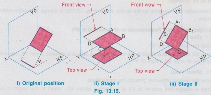
Engineering Graphics: Unit II (d): Projections of Planes : Tag: : Projections of Planes | Engineering Graphics (EG) - Change of Position Method
Related Topics
Related Subjects

Engineering Graphics
GE3251 eg 2nd semester | 2021 Regulation | 2nd Semester Common to all Dept 2021 Regulation