Theory of Machines: Unit V: Balancing and Vibration
balancing of several masses rotating in different planes [dalby's method]
Balancing and Vibration - Theory of Machines
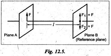
The technique of tackling this problem is to transfer the centrifugal force acting in each plane to a single parallel plane which is usually termed as reference plane (R.P.).
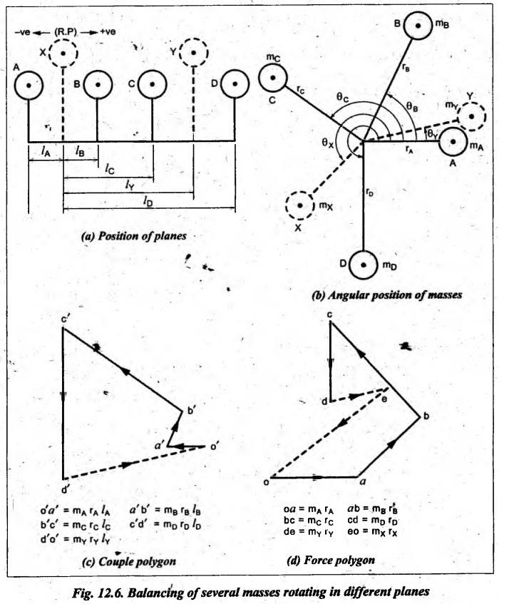
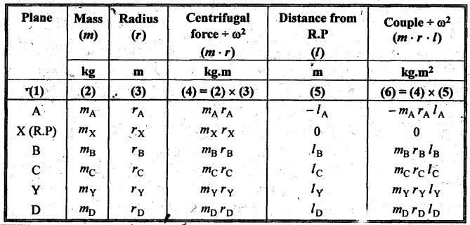
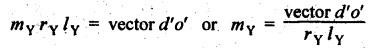
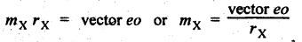
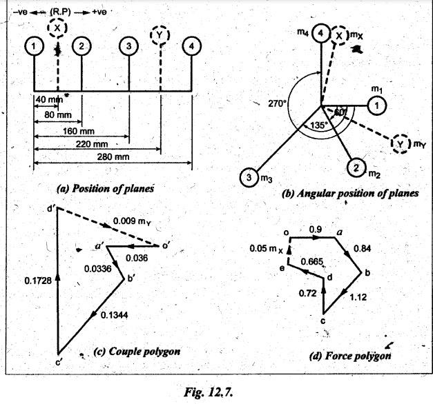
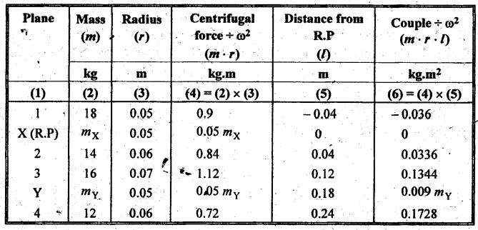
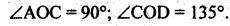
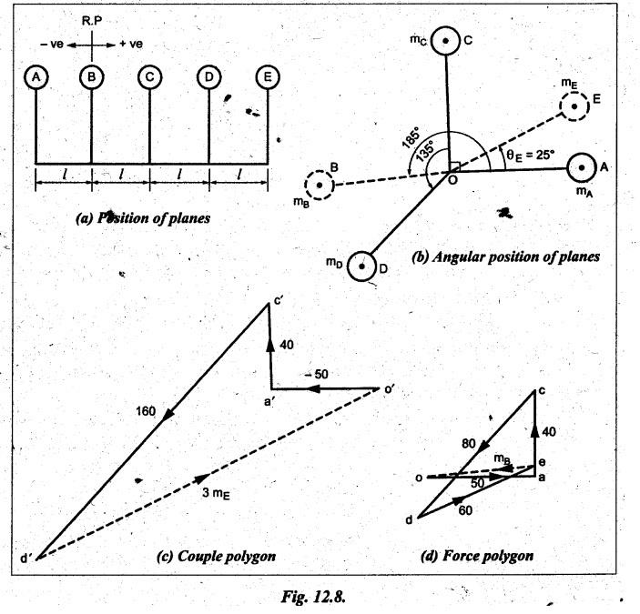
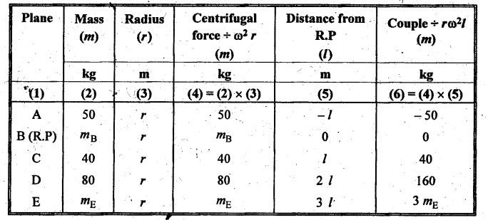
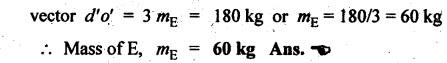
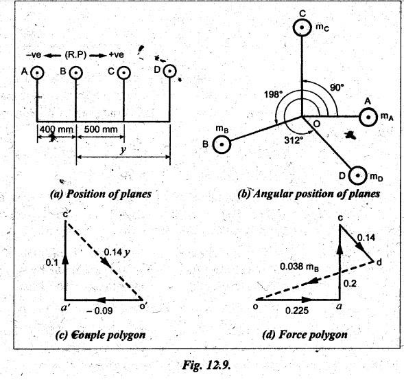
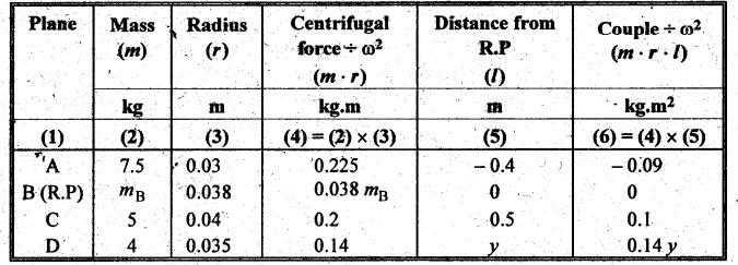
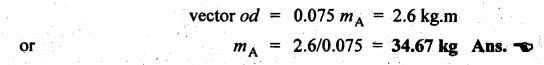
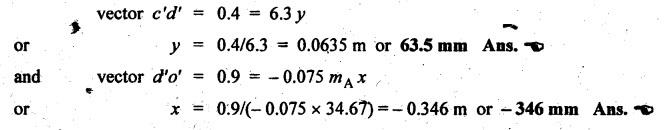
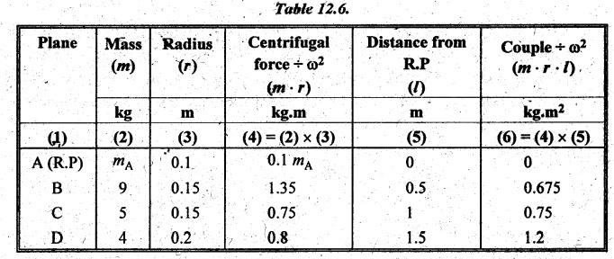
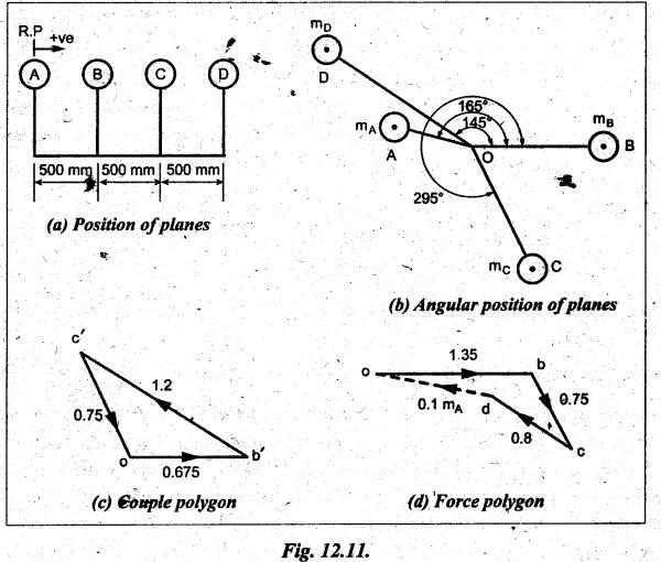
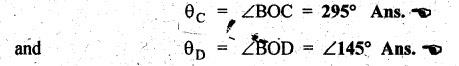
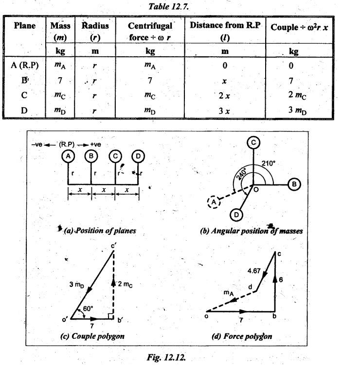
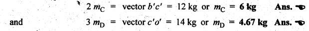
BALANCING OF SEVERAL MASSES ROTATING IN DIFFERENT PLANES [DALBY'S METHOD] The technique of tackling this problem is to transfer the centrifugal force acting in each plane to a single parallel plane which is usually termed as reference plane (R.P.). Then the procedure for balancing is almost the same as for different forces acting in the same plane. The transference of a force from one plane to another plane is explained as given below. Consider a force F acts radially outward in plane A and it is intended to transfer this force to another parallel plane (B) called reference plane which is situated at a distance of 'l' from the plane A, as shown in Fig.12.5. Now introduce two equal and opposite forces F1 and F2, both being parallel to force F, in the reference plane. The equilibrium of the system does not change due to the introduction of forces F1 and F2. The net effect would be a single force F1 in the reference plane having the direction of the original force F along with a couple of magnitude F × l formed by the forces F and F2. Thus the effect of transferring a force F acting in one plane to another plane (reference plane) is equivalent to transfer of the same force F in magnitude and direction in thẹ reference plane accompanied by a couple of magnitude F • l. In order to have the complete balance of the several rotating masses in different planes, the following two conditions must be satisfied. 1. The resultant centrifugal force must be zero, and 2. The resultant couple (ie., the couple about the reference plane) must be zero. Let us consider any number of masses (say, four masses m1, m2, m3 and m4 revolving in planes A, B, C and D respectively, as shown in Fig.12.6(a). The relative angular positions of various masses are shown in the side view [Fig.12.6(b)]. Let mX and mY be the balancing masses to be introduced in planes X and Y respectively. Procedure of Balancing 1. Take any one of the planes, say X, as this reference plane are taken with the reference plane (R.P.). Distances to the left of this reference plane are taken with negative sign and those to right with positive sign. 2. Tabulate the forces and couples as shown in Table 12.1. It may be noted that the planes (in column (1)) are tabulated in the same order which they occurs from left to right (in Fig.12.6(a)). Table 12.1. Note Centrifugal force and couple are to be taken proportional to m r and m r l respectively as ω2 is common to both. 3. The next step is to draw the couple polygon. Couple mA rA lA is negative with respect to the reference plane. So the couple (- mA rA lA) is drawn radially inwards as it is in the reverse direction of OmA. Couple mB rB lB is positive with respect to reference plane, so the couple is drawn radially outwards i.e., in the direction of OmB. Similarly, couples mC rC lC and mD lD are drawn to scale and in the directions of OmC and OmƊ respectively. Couple mY rY lY is the closing side, as shown in Fig.12.6(c). From this expression, the value of the balancing mass mY in the plane Y can be determined. The angle of this mass (θY) can be measured from Fig.12.6(b). 4. Now draw the force polygon from the data given in Table 12.1 column (4), as shown in Fig.12.6(d). The vector eo represents the balanced force. Since the balanced force is proportional to mX rX therefore, From the above expression, the value of the balancing mass mX in the plane X can be obtained. The angle of inclination (θX) of this mass with the horizontal can be measured from the Fig. 12.6(b). • It may be noted here that the couple polygon is drawn first. This is because in Table 12.1, in centrifugal force column (4), we have two unknowns mX and mY, so force cannot be constructed first. But in Table 12.1, in couple column (6), we have only one unknown in terms of mY, so the couple polygon has to be drawn first to obtain the magnitude and direction of mY. Example 12.2 A rotating shaft carries four unbalanced masses 18 kg, 14 kg, 16 kg and 12 kg at radii 5 cm, 6 cm, 7 cm and 6 cm respectively. The 2nd, 3rd and 4th masses revolve in planes 8 cm, 16 cm and 28 cm respectively measured from the plane of the first mass and are angularly located at 60%, 135° and 270° respectively measured clockwise from the first mass looking from this mass end of the shaft. The shaft is dynamically balanced by two masses, both located at 5 cm radii and revolving in planes mid-way between those of 1 and 2 masses and mid-way between those of 3rd and 4th masses. Determine graphically or otherwise, the magnitudes of the masses and their respective angular positions. Given data: m1 = 18 kg; r1 = 5 cm; θ1 = 0° (assuming m1 lies horizontally); m2 = 14 kg; r2 = 6 cm; θ2 = 60°. m3 = 16 kg; r3 = 7 cm; θ3 = 135°; m4 = 12 kg; r4 = 6 cm; θ4 = 270° Solution: Let us consider the two balancing masses are mX and mY in planes X and Y respectively. The position of the planes and angular positions of masses are shown in Fig.12.7(a) and (b) respectively. Here the position of mass m1 is assumed to be in horizontal direction. Since mX and mY are to be found, we can take either plane X or plane Y as reference plane. Taking plane X as the reference plane, and considering the distances of the right of this plane as positive while to the left as negative, the various data may be tabulated as shown in Table 12.2. Table 12.2. Procedure: 1. First of all, draw the couple polygon from the data given in column (6) of Table 12.2, as shown in Fig.12.7(c) to some suitable scale (say, 1 shown in Fig. 12.7(c) to some suitable scale (say, 1 cm = 0.025 kg.m2). The closing side of the polygon i.e., vector d'o' represents the balancing couple and it is proportional to 0.009 mY. Therefore, by measurement 2. The angular position of mass mY is determined by drawing O mY in Fig.12.7(b), parallel to vector d'o' in the same direction. By measurement, angular position of mass mY is θY = 25 in the clockwise direction from mass 3. Now draw the force polygon from the data given in column (4) in Table 12.2, as shown in Fig.12.7(d), to some suitable scale (say, 1 cm - 0.5 kg.m). The closing side of the polygon i.e., vector eo represents the balancing force and it is proportional to 0.05 mX. Therefore, by measurement 4. The angular position of mass my is determined by drawing O mX in Fig.12.7(b), parallel to vector eo. By measurement, angular position of mass mX is θX = 275° in the clockwise direction from mass m1 Ans. Example 12.3 A shaft carries five masses A, B, C, D and E which revolve at the same radius in planes which are equidistant from one another. The magnitude of A, C, D are 50 kg, 40 kg and 80 kg respectively. The angle between A and C is 90° and that between C and D is 135°. Determine the magnitude of the masses in planes B and E and their positions to put the shaft in complete rotating balance. Given data: rA = rB = rC = rD = rE = r; mA = 50 kg; mC = 40 kg; mD = 80 kg; Solution: The position of planes and angular positions of masses are shown in Fig.12.8(a) and (b) respectively. Since m and my are to be found, we can take either plane B or plane E as reference plane. Taking plane B as the reference plane, and considering the distances of the right of this plane as positive while to the left as negative, the various data may be tabulated as shown in Table 12.3. Table 12.3. Procedure: 1. First of all, draw the couple polygon using the data in column (6) of Table 12.3, as shown in Fig.12.8(c), to some suitable scale (say, 1 cm = 20 kg). We know that for a complete balance, the couple polygon must be a closed figure. The closing side of the polygon i.e., vector d'o' is proportional to 3 mE... By measurement, 2. The angular position of mass my is determined by drawing OE in Fig.12.8(b), parallel to vector d'o' in the same direction. By measurement, angular position of mass mE is θE = 25° measured from mass A in counter clockwise direction. Ans. 3. Now, draw the force polygon from the data given in the column (4) of Table 12.3, as shown in Fig.12.8(d), to some suitable scale (say, 1 cm 20 kg). The closing side of the polygon i.e., vector eo is proportional to mg. By measurement to the chosen scale, 4. The angular position of mass B is determined by drawing OB in Fig.12.8(b), parallel to vector eo in the same direction. By measurement, angular position of mass mp is θB = 185° measured from mass A in counter clockwise direction. Ans. Example 12.4 A rotating shaft carries four masses A, B, C and D which are radially attached to it. The mass centres are 30 mm, 38 mm, 40 mm and 35 mm respectively from the axis of rotation. The masses A, C and D are 7.5 kg, 5 kg and 4 kg respectively. The axial distances between the planes of rotation of A and B is 400 mm and between B and C is 500 mm. The masses A and C are at right angles to each other. Find for a complete balance: 1. the angle between the masses B and D from mass A, 2. the axial distance between the planes of rotation of C and D, and 3. the magnitude of mass B. Given data: Solution: Let mB = Magnitude of mass B, and y = Distance of plane D from plane B. The position of the planes and angular position of the masses are shown in Figs.12.9(a) and (b) respectively. Here the position of mass A is assumed to be in horizontal direction. Taking plane B as the reference plane, and considering the distances of the right of this plane as positive while to the left as negative, the various data may be tabulated as shown in Table 12.4. Procedure: 1. First of all, draw the couple polygon using the data in column (6) of Table 12.4, as shown in Fig.12.9(c), to some suitable scale (say, 1 cm = 0.04 kg.m2). We know that for a complete balance, the couple polygon must be a closed figure. The closing side of the polygon i.e., vector b'o' is proportional to 0.14 y. By measurement, 2. The angular position of mass mò is determined by drawing OD in Fig12.9(b), parallel to vector b'o' in the same direction. By measurement, angular position of mass mD is p θD = 312° measured from mass A in counter clockwise direction. Ans. 3. Now, draw the force polygon from the data given in the column (4) of Table 12.4, as shown in Fig.12.9(d), to some suitable scale (say, 1 cm = 0.09 kg.m). The closing side of the polygon i.e., vector do is proportional to 0.038 mB. By measurement to the chosen scale, 4. The angular position of mass B is determined by drawing OB in Fig.12.9(b), parallel to vector do in the same direction. By measurement, angular position of mass mB is θB = 198° measured from mass A in counter clockwise direction. Ans. Example 12.5 A shaft carries four rotating masses A, B, C and D which completely balanced. The masses B, C and D are 50 kg, 80 kg and 70 kg respectively. The masses C and D make angles of 90° and 195° respectively with mass B in the same sense. The masses A, B, C and D are concentrated at radius 75 mm, 100 mm, 50 mm and 90 mm respectively. The plane of rotation of masses B and C are 250 mm apart. Determine: (i) the magnitude of mass A and its angular position, and (ii) the position of planes A and D. Procedure: 1. First of all, draw the force polygon using the data in column (4) of Table 12.5, as shown in Fig.12.10(c), to some suitable scale (say, 1 cm = 1 kg.m). (Since there are two unknowns in column (6), couple polygon cannot be drawn first). We know that for a complete balance, the polygon must be closed figure. The closing side of the polygon i.e., force vector od is proportional to 0.075 mA. By measurement, 2. The angular position of mass mA is determined by drawing OA in Fig.12.10(b), parallel to vector od in the same direction. By measurement, angular position of mass mA is θA = 295° measured from mass B in counter clockwise direction. Ans. 3. Now, draw the couple polygon from data given in the column (6) of Table 12.5, as shown in Fig.12.10(d), to some suitable scale (say, 1 cm = 0.5 kg.m2). Here from c' and o', draw lines parallel to OD and OA, such that they intersect at d'. As the system is in complete balance, the couple polygon must be a closed figure. By measurement, Here -ve sign indicates that the plane A is 346 mm towards right of reference plane (i.e., plane B). Now the actual position of planes can be drawn as shown in Fig.12.10(e). Example 12.6 A, B, C and D are four masses carried by a rotating shaft at radii 100 mm, 150 mm, 150 mm and 200 mm respectively. The planes in which the masses rotates are spaced at 500 mm apart and the magnitude of the masses B, C and D are 9 kg, 5 kg and 4 kg respectively. Find the required mass A and the relative angular settings of the four masses so that the shaft must be in complete balance. Given data: rA = 100 mm = 0.1 m; rB = 150 mm = 0.15 m; rC = 150 mm = 0.15 m; rD = 200 mm = 0.2 m; mB = 9 kg; mC = 5 kg; mD = 4 kg. Solution: The position of planes is shown in space diagram as shown in Fig.12.11(a). Taking plane A as the reference plane, various data may be tabulated as shown in Table 12.6. Procedure: 1. First of all, draw the couple polygon using the data in column (6) of Table 12.6, as shown in Fig.12.11(c), to some suitable scale (say, 1 cm = 0.3375 kg.m2), as follows: • In order to start with, let us assume the angular position of mass B is in horizontal direction. So, draw vector o'b' in the horizontal direction (i.e., parallel to OB) and equal to 0.675 kg.m2 to the scale. • From points o' and b' draw vectors o'c' and b'c' equal to 0.75 kg.m2 and 1.2 kg.m2 respectively. These vectors (arcs) intersect at c'. Now joining b'c' and c'o', we get the couple polygon, as shown in Fig.12.11(c). 2. Now in Fig.12.11(b) draw OC parallel to vector o'c' in the same direction and OD parallel to vector b'c' in the same direction. By measurement, the angular setting of masses Ċ and D in the anticlockwise direction measured from mass B are given by 3. In order to find MA draw the force polygon from the data given in column (4) of Table 12.6, as shown in Fig.12.11(d), to some suitable scale (say, 1 cm = 0.45 kg.m). Since the closing side of the force polygon i.e., vector do is proportional to 0.1 mA, therefore by measurement 4. In order to find the direction of mA, draw OA parallel to vector od in the same direction in Fig.12.11(b). By measurement, the angular position of mass A in the anticlockwise direction measured from mass B is given by Example 12.7 Four masses A, B, C and D revolve at equal radii and are equally spaced along a shaft. The mass B is 7 kg and the radii of C and D make angles of 90° and 240° respectively with the radius of B. Find the magnitude of the masses A, C and D and the angular position of A so that they system may be completely balanced. Given data: Solution: Let r = Radius of rotation of each mass, and x = Distance between consecutive planes. The position of the planes and angular position of the masses are shown in Fig.12.12(a) and (b) respectively. Assuming plane A as reference plane, the various data may be tabulated as shown in Table 12.7. Procedure: 1. First it is assumed that the plane B is in horizontal direction. Since the given system is completely balanced, the couple polygon should be closed. Draw vector o'b' using some suitable scale (say, 1 cm = 2 kg) in the horizontal direction and draw a perpendicular line at b' in the direction of OC. Now draw a line 60° inclined in the direction of OD so as to intersect the perpendicular line from o' at c', as shown in Fig.12.12(c). 2. In Fig.12.12, the vector b'c' is proportional to 2 mC and vector o'c' is proportional to 3 mD. By measurement, we get 3. Now draw the force polygon using the data in column (4) of Table 12.7, as shown in Fig.12.12(d), using some suitable scale (say, 1 cm = 2 kg). The closing side of the polygon represents force due to mass A. By measurement, we get 4. The angular position of mass A is determined by drawing a parallel line OA in Fig.12.12(b), parallel to vector do in the same direction. By measurement, we get 1. Transference of a Force from One Plane to Another Plane
2. Conditions for Complete Balancing
3. Illustration


![]()
![]()

![]()


![]()

![]()
![]()


Theory of Machines: Unit V: Balancing and Vibration : Tag: : Balancing and Vibration - Theory of Machines - balancing of several masses rotating in different planes [dalby's method]
Theory of Machines: Unit V: Balancing and Vibration
Under Subject

Theory of Machines
ME3491 4th semester Mechanical Dept | 2021 Regulation | 4th Semester Mechanical Dept 2021 Regulation
Related Subjects

Environmental Sciences and Sustainability
GE3451 ESS 4th Semester | 2021 Regulation | 4th Semester EEE Dept 2021 Regulation
Theory of Machines
ME3491 4th semester Mechanical Dept | 2021 Regulation | 4th Semester Mechanical Dept 2021 Regulation

Thermal Engineering
ME3451 4th semester Mechanical Dept | 2021 Regulation | 4th Semester Mechanical Dept 2021 Regulation

Hydraulics and Pneumatics
ME3492 4th semester Mechanical Dept | 2021 Regulation | 4th Semester Mechanical Dept 2021 Regulation

Manufacturing Technology
ME3493 4th semester Mechanical Dept | 2021 Regulation | 4th Semester Mechanical Dept 2021 Regulation
Strength of Materials
CE3491 4th semester Mechanical Dept | 2021 Regulation | 4th Semester Mechanical Dept 2021 Regulation