Engineering Graphics: Unit III (b): Projections of Solids
Axis Inclined to one of the Reference Planes
Projections of Planes | Engineering Graphics (EG)
If axis of a solid is inclined to one of the reference planes it is evident that the axis will be parallel to other plane.
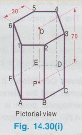
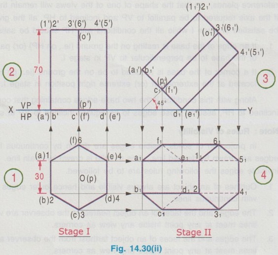
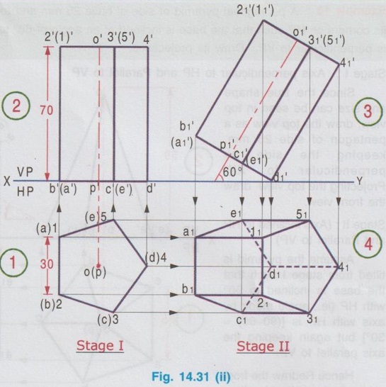
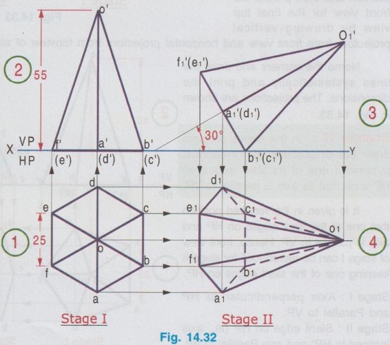
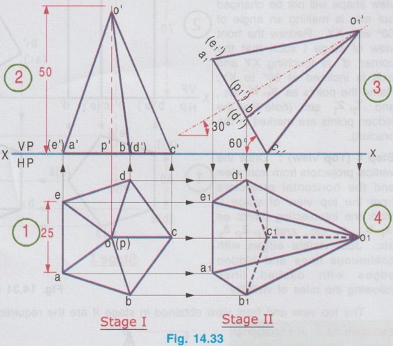
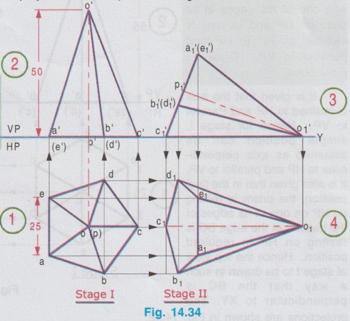
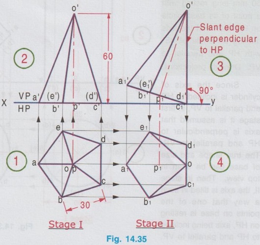
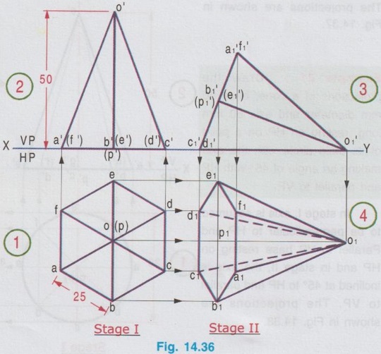
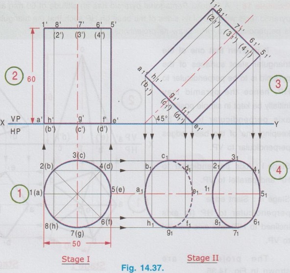
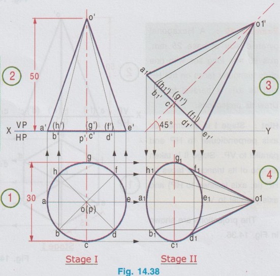
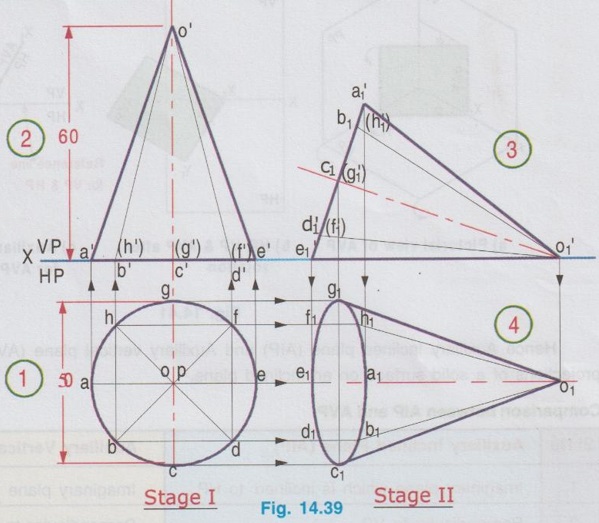
AXIS INCLINED TO ONE OF THE REFERENCE PLANES If axis of a solid is inclined to one of the reference planes it is evident that the axis will be parallel to other plane. The projection of solid with axis inclined to one plane and paralled to other plane is drawn in similar way to that explained for plane figures in the last chapter, but the height of the solid (ie third dimension) is also to be considered. Projections of solids having axis inclined to one plane and parallel to the other plane cannot be directly drawn, since the base of such a solid will not be parallel to any one of the reference planes its true shape cannot be drawn in any of the views. Such problems can be solved by two methods, namely (i) Change of position method and (ii) Auxiliary plane method. In change of position method, two stages are considered. Stage 1 : The solid is assumed to have its axis perpendicular to the plane with which it is required to be inclined. Stage II: Tilting the axis to the angle about the plane and drawing the final projections. Therefore when the axis is inclined to HP and parallel to VP, then consider the stages as below: Stage 1 : Assume the axis is perpendicular to HP and Parallel to VP and draw the views. Stage II: Tilt the axis inclined to HP but again parallel to VP and draw the final projections. Similarly if the axis is inclined to VP and parallel to HP, then consider the stages as below: Stage 1 : Assume the axis is perpendicular to VP and Parallel to HP and draw the views. Stage II: Tilt the axis inclined to VP but again parallel to HP and draw the final projections. Stage I is known as "simple position" and Stage II is known as "Tilted position (or) Final position". The method of drawing projections of these two cases are presented in detail in the following articles. CASE 2(A): PROJECTIONS OF SOLIDS WITH AXIS INCLINED TO HP AND PARALLEL TO VP BY CHANGE OF POSITION METHOD. Let a rectangular pyramid is inclined at an angle θ to HP and parallel to VP for which the projections are to be drawn. Since the true shape and size cannot be seen in any view, the projections are drawn in two stages. Stage 1 : Axis perpendicular to HP and parallel to VP. Stage II: Axis inclined at θ to HP and parallel to VP. The pictorial view of these two stages are shown in Fig. 14.28. In stage I, when the axis is assumed perpendicular to HP, the base is parallel to HP and hence the true shape and size can be drawn in topview. Front view will be a triangle. Hence draw the topview first and project the topview for front view. Then in Stage II, tilt the axis to angle θ with HP (ie. required inclination) but without affecting the position of axis with VP ie., keeping the axis again parallel to VP as shown in Fig. 14.28. As the axis is again made parallel to VP, the front view of stage I can be reproduced but with axis inclined at θ to XY. Then by projecting the front view the final top view can be drawn. Hence in stage II, draw the front view first and then draw the top view. The projections in Stage I and Stage II are presented in Fig. 14.29. Note: When additional conditions are to be satisfied When there are additional conditions to be satisfied along with axis being parallel to VP and inclined to HP, it is necessary that the initial position of the solid be so selected that when the solid is tilted from the stage I to stage II, the lines and points will not change their relation with one of the reference planes, so that the shape of one of the views will remain the same. A general rule is that if the axis required to be parallel to VP and inclined to HP, all the given conditions with VP should be satisfied in stage I while all the conditions with HP should be satisfied in stage II. 1. If an edge of the base is resting on the ground (ie., on HP) (or) parallel to HP, assume that edge of the base to be perpendicular to VP in stage I. 2. If a corner of the base is required to be on the ground (ie., on HP), assume that corner to be located at the extreme left (or) extreme right position in stage I. Along with this condition if the two base edges containing that corner are required to be equally inclined to HP, assume those edges to be equally inclined to VP in stage I. Note: Rules of Visibility In projection of solids, visible edges are drawn by continuous line and the invisible (hidden) edges are drawn by dashed line. Axis of solid is drawn by chain line. In connection with visible and invisible edges the following rules are to be followed. 1. Outlines of an object are always visible and hence outer edges of any view should be drawn with continuous lines. 2. The edges and the faces of an object nearest to the observer are visible, hence, three continuous lines meet at any point inside any view as corners. 3. The edges and the faces of an object farthest from the observer are hidden, hence three hidden lines meet at any point inside any view as corners. 4. Two continuous lines never cross each other inside any view. 5. Two hidden lines never cross each other inside any view. Example 13: A Hexagonal prism having base with 30 mm side and 70 mm long axis has an edge of its base on HP. Its axis is parallel to VP and inclined at 45° to HP. Draw its projections. The prism is visualised and the corners are named as shown in Fig. 14.30(i). It is given that one of the edges lies on HP. Let the edge DE is on HP. Hence draw the edge perpendicular to XY in stage I. As the required position to be the axis inclined to HP and parallel to VP, the two stages are assumed as below: Stage I (Simple position) : Axis perpendicular to HP and parallel to VP. Stage II (Final position) : Axis inclined to HP and parallel to VP. Step 1 (Top view): Draw the reference line XY. Since the edge DE of prism lies on HP draw a hexagon abcdef with side de perpendicular to XY as top view. Step 2 (Front view): Draw the vertical projectors through the corners and obtain the front view, as a rectangle having its bottom edge coincides with XY since the prism rests on HP. Name the points systematically. Step 3 (Front view): Now ari keeping the axis again parallel to VP, axis is tilted such that it is inclined to 45° with HP. Hence the front view shape will not be changed but axis is making an angle of 45° with XY. Redraw the front view of stage I such that the edge d'e' is in contact with XY and the axis is inclined at 45° to XY line. Name the points as a'1, b'1 etc., and 1'1, 2'1 etc. (note that the hidden points are written in the bracket). The top view and front view obtained in stage II are the required projections. Example 14: A pentagonal prism, having base with a 30 mm side and 70 mm long axis has a corner of its base on the ground and axis is inclined at 60° to HP. Draw the projections of the pentagonal prism if the plane containing that corner and the axis is parallel to VP. Given Condition: It is given that pentagonal prism is resting on ground with a corner and the plane containing the corner and the axis is parallel to VP. The pentagonal prism is visualised and the corners are named as shown in Fig. 14.3(i). Let the prism is resting on the corner D. Stages Assumed Stage I : (Axis Perpendicular to HP & Parallel to VP); Stage II : (Axis Inclined to HP & Parallel to VP); Step 1 (Top view): Draw the reference line XY. Draw a pentagon abcde as topview in such a way that the line joining the corner D and centre of pentagon is parallel to XY. (since the Pentagon is to rest on HP about the corner D in stage II). Step 2 (Front view): Draw the vertical projectors through the corners and obtain the front view, as a rectangular boundary, bottom edge, coinciding with XY, since the prism rests on HP. Name the points systematically. Step 3 (Front view) : Now, keeping the axis again parallel to VP, tilt the axis such that it is inclined to 60° with HP and about the corner D. Hence the front view shape will not be changed but axis is making an angle of 60° with XY. Redraw the front view of stage I such that the corner d' is touching XY and axis is inclined at 60° to XY. Name the points as a'1, b'1 etc., and 1'1, 2'1 etc., (note that the hidden points are marked in the bracket). Step 4 (Top view): Draw the vertical projectors from front view and the horizontal projectors from the top view of stage 1. Mark the intersecting points as a1, b1, c1 etc., and 11, 21, 31 etc., Join visible edges with continuous lines and hidden edges with dashed lines following the rules of visibility. The top view and front view obtained in stage II are the required projections. Example 15: A Hexagonal pyramid, side of base 25 mm and axis 55 mm long rests with one of the edges of its base on HP and its axis is inclined at 30° to HP and parallel to VP. Draw its projections. It is given that the axis is inclined to HP and Parallel to VP. Hence for stage I, simple position can be assumed as axis perpendi- cular to HP and parallel to VP. It is also given that in the final position, the prism is resting on HP on one of its edges of the base. Let the edge BC is resting on HP in required position. Hence the top view of stage I to be drawn in such a way that the BC is perpendicular to XY. The projections are shown in Fig. 14.32. Example 16: A pentagonal pyramid of side of base 25 mm and axis 50 mm long rests with one of its corners on HP such that the base is inclined at an angle of 60° to HP and one of the side of base is perpendicular to VP. Draw its projections. Stage I : Axis perpendicular to HP and Parallel to VP Since the true shape and size can be seen in top view, draw the top view as a pentagon of side 25 mm, keeping the side ae perpendicular to XY. Projecting the top view draw the front view. Stage II: (Axis inclined to HP and Parallel to VP) Assume the pyramid is tilted from stage I such that the base is inclined to 60° with HP (ie., angle made by axis with HP is [(90-60) = 30°] but again keeping the axis parallel to VP. Hence Redraw the front view of stage I with tilting position and then project the front view for the final top view by drawing vertical projectors from front view and horizontal projectors from topview of stage I. Name the corners and draw the lines systematically and print the dimensions. The projections are shown in Fig. 14.33. Example 17: In the above problem draw the projections of Pentagonal pyramid if one of its slant edges on HP such that its axis is parallel to VP. It is given in the required position that one of the slant edges on HP and axis is parallel to VP. Hence, front view of stage I can be reproduced for stage II keeping one of the slant edges on HP. Stage I : Axis perpendicular to HP and Parallel to VP. Stage II : Slant edge on HP (ie., axis inclined to HP) and axis Parallel to VP. The projections are shown in Fig. 14.34. Example 18: A Regular Pentagonal pyramid has an altitude of 60 mm and base side 30 mm. The pyramid rests with one of its sides of the base on HP such that the triangular face containing that side is perpendicular to HP. Draw its projections. It is given that one of the triangular slant surfaces of the pyramid is to be perpendicular to HP, hence the pyramid may initially be kept in simple position, axis perpendicular to HP by keeping one of the base edges perpendicular to VP. Stage I: Axis perpendicular to HP and parallel to VP. Stage II : Slant edge perpendicular to HP (ie axis inclined to HP) and axis parallel to VP. The projections are shown in Fig. 14.35. Example 19: A Hexagonal pyramid side of base 25 mm, axis 50 mm long lies with one of its triangular faces on the HP and its axis is parallel to VP. Draw its projections. Hint: Stage I is assumed as axis perpendicular to HP and parallel to VP. Stage II is taken as one of its triangular faces on HP (ie, axis inclined to HP) and axis parallel to VP. The projections are shown in Fig. 14.36. Example 20 : A right circular cylinder of base 50 mm diameter and axis 60 mm long resting with a point of its base circle on HP such that the axis making an angle of 45° with HP and parallel to VP. Draw its projections. Since the axis of X cylinder is inclined to HP and parallel to VP, in first stage it is assumed that axis is perpendicular to HP and parallel to VP. The true shape and size of base can be seen in top view. Then in stage II, the axis is tilted in such a way that one of the points on base is resting on HP, axis being inclined to HP and parallel to VP. The projections are shown in Fig. 14.37. Example 21 : Draw the projections of a cone, base 30 mm diameter and axis 50 mm long, resting on HP on a point of its base circle with the axis making an angle of 45° with HP X and parallel to VP. In stage I, axis is assumed to be perpendicular to HP and Parallel to VP base resting on HP and in stage II, the axis is inclined at 45° to HP and parallel to VP. The projections are shown in Fig. 14.38. Example 22: A cone of base 50 mm diameter and axis 60 mm long has one of its generators on HP. If the axis is parallel to VP, draw its projections. Stage I : Axis of cone perpendicular to HP and parallel to VP. Draw the topview first and then draw the front view. Stage II: One of the generators on HP (ie. axis inclined to HP) and axis parallel to VP. Reproduce the front view from stage I keeping one of the generators on HP. Then draw the topview by projecting from front view and the top view of stage I. The front view and top view obtained in stage II are the required projections. The projections are shown in Fig. 14.39.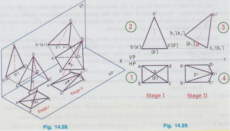
 Step 4 (Top view): Draw the vertical projectors from front view and the horizontal projectors from the topview of stage I. Mark the intersecting points as a1, b1 etc., and 11, 21 etc., Join visible edges with continuous lines and hidden edges with dashed lines, following the rules of visibility.
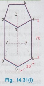
Engineering Graphics: Unit III (b): Projections of Solids : Tag: : Projections of Planes | Engineering Graphics (EG) - Axis Inclined to one of the Reference Planes
Related Topics
Related Subjects

Engineering Graphics
GE3251 eg 2nd semester | 2021 Regulation | 2nd Semester Common to all Dept 2021 Regulation