Engineering Graphics: Unit III (b): Projections of Solids
Axis Inclined to both the Planes
Engineering Graphics (EG)
If the axis is inclined to only one plane it is evident that the axis will be parallel to another plane.
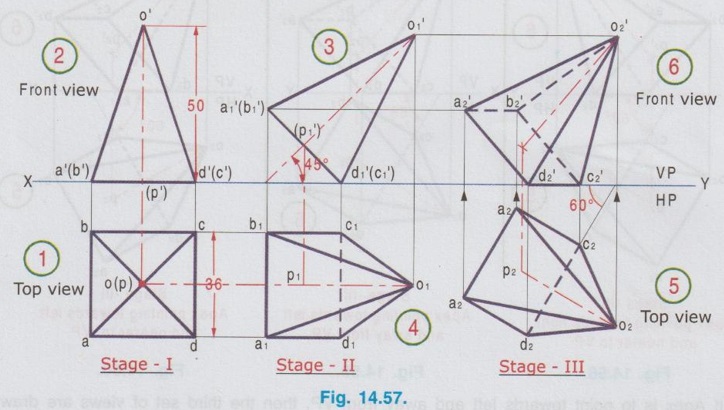
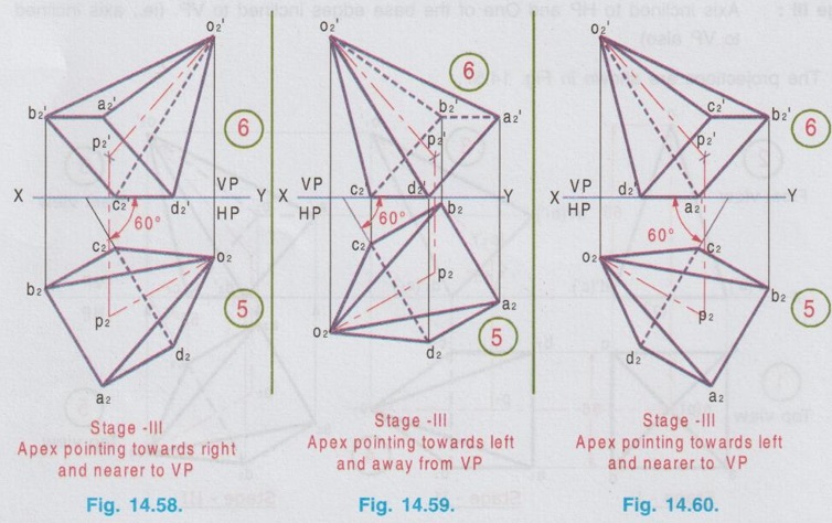
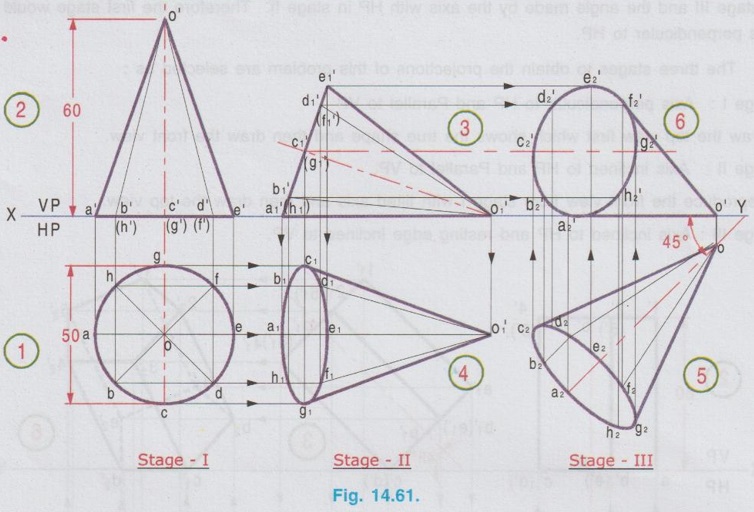
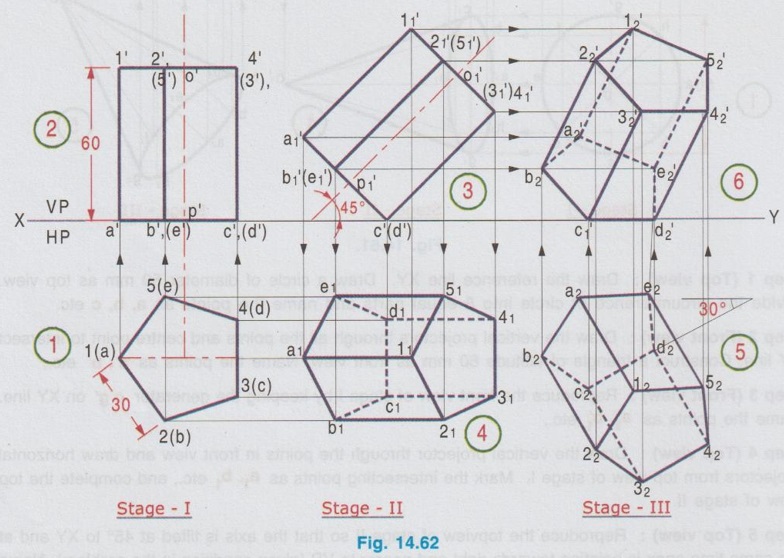
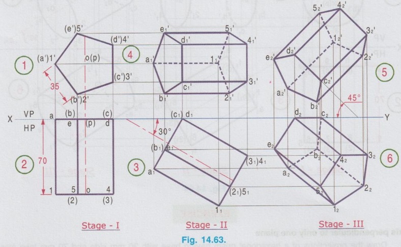
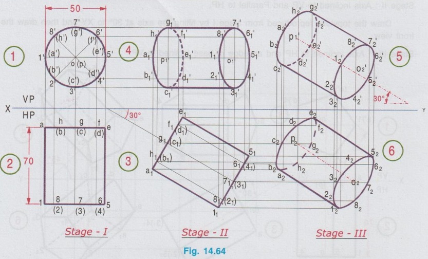
AXIS INCLINED TO BOTH THE PLANES So far we have drawn the projections of solids with axis inclined to only one reference plane (either HP or VP). If the axis is inclined to only one plane it is evident that the axis will be parallel to another plane. Hence for this type of problems, two stages were followed to draw the projections in change of position method. Stage I, simple position and stage II, tilted (or) required position. Now the projections of solids, axis being inclined to both the reference planes (both HP and VP) are discussed in this article. It is an extension of the procedure followed for the axis inclined to only one plane. When the axis of a solid is inclined to both HP and VP, its projections can be obtained in three stages as below: Stage 1: The axis of the solid is kept in simple position (ie., perpendicular to one of the reference planes and parallel to the other). With this condition the first set of views are drawn. Stage II: The solid is tilted to bring the axis inclined to the reference plane about which axis made perpendicular in stage I and parallel to the other plane. With this tilted position the second set of views are drawn. Stage III: The solid is further tilted to bring the axis inclined to both the reference planes about which axis made parallel in stage I and stage II. Now the axis becomes inclined to both the planes. The third set of views, drawn in this final stage are the required projections. It is very important to note that, the position of the solid should be initially so selected in such a way that i) When it is tilted from stage I to stage II, all points, lines and planes of the solid will change their relations with only one of the reference planes and ii) Will change the relations with the other reference plane only when it is tilted from stage II to stage III position. Also note that, All the given conditions should be satisfied between stage II and stage III. None of the given conditions should be satisfied in stage I. Note: 1. As the solid is inclined to both the planes, two angles of inclinations will be given in the problem, one with HP and another with VP. 2. The inclination of the axis can be given directly (or) indirectly through angles made by i) a side surface, or ii) any other line, or iii) base of the solid 3. If the angle made by the base surface is known, it is as good as the axis angle given. Because if the angle made by the base surface is θ, then the angle made by the axis will be (90 - θ) as shown in fig. Example 36: A square pyramid has its axis inclined at 45° to HP and one edge of its base is inclined at 60° to VP. The edge of the base is 36 mm and the height is 50 mm. Draw the projections of the square pyramid, keeping one of the edges of its base on HP. Required Conditions 1. Axis inclined to HP at 45°. 2. One of the base edges inclined to VP at 60°. 3. One of the base edges on HP. Stages Assumed er Let us keep the angle made by the base edge with VP in stage III (for this one of the base edges may be drawn on HP ie., XY line). So, we will consider the angle made by the axis with HP in stage II. As the axis is to be inclined to HP in stage II, the first stage should be, the axis perpendicular to HP. Hence the three stages considered to get the final projections of the given solid are : Stage 1 : Axis perpendicular to HP and Parallel to VP. Stage II : Axis inclined to HP and Parallel to VP. Stage III: Axis inclined to HP and One of the base edges inclined to VP. (ie., axis inclined to VP also) The projections are shown in Fig. 14.57. Step 1 (Top view): Draw the reference line XY. Draw the topview as a square of side 36 mm (since the base is parallel to HP), keeping one of the base edges perpendicular to VP and name the corners as a, b, c and d. Step 2 (Front view): Draw the vertical projectors through the points and centre point and draw the front view as a triangle of altitude 50 mm, which represents axis length. Name the corners in front view as a', b', c' and d' (Hidden edges are shown within the bracket). Step 3 (Fron view): Reproduce the front view of stage I with axis inclined at 45° to xy, assuming the edge d-c is on HP. Name the corners as a'1, b'1 etc., Step 4 (Top view): Draw the vertical projectors through all the points in front view and draw the horizontal projectors from topview of stage I. Mark the intersecting points as a1, b1 etc., and join the points with continuous lines for visible edges and dashed lines for hidden edges. Step 5 (Top view): Reproduce the topview of stage II, keeping the edge. c1, d1 inclined at 60° to XY line which is the required top view. Mark the points as a2, b2 etc., Step 6 (Front view): Draw the vertical projectors through all the corners in topview and draw horizontal projectors from front view of stage II. Mark the intersecting points as a'2, b'2 etc., Join the points by continuous thick lines for visible edges and short dashed lines for hidden edges. The projections obtained in step 5 and step 6 are the required topview and front view. Note: In the above problem, the position of apex with reference to VP is not given. Hence it was assumed that apex pointing towards right and away from VP. i) Suppose the apex to point towards right and nearer to VP, then the third set of views are drawn as shown in Fig. 14.58. (no change in first and second set of views) ii) If Apex is to point towards left and away from VP, then the third set of views are drawn as shown in Fig. 14.59. iii) If the apex is to point towards left and nearer to VP, then the third set of views are drawn as as shown in Fig. 14.60. Example 37: A cone of base diameter 50 mm and 60 mm height has one of its generators on HP. If the axis of the cone is seen as 45° inclined to XY line in the top view and the apex is nearer to VP, draw the projections of the cone. It is given that one of the generators of cone on HP (ie axis inclined to HP) and axis inclined to VP at 45°. Also the apex is to be nearer to VP. Hence the different stages of solid to obtain the required projections are assumed as below: Stage 1: Axis perpendicular to HP and Parallel to VP. Stage II : One of the generators on HP (ie., axis inclined to HP) and axis parallel to VP. Stage III: One of the generators on HP (ie., axis inclined to HP) and axis inclined to VP. The projections are shown in Fig. 14.61. Step 1 (Top view): Draw the reference line XY. Draw a circle of diameter 50 mm as top view. Divide the circumference of circle into 8 equal parts and name the points as a, b, c etc. Step 2 (Front view): Draw the vertical projectors through all the points and centre point to intersect XY line. Construct a triangle of altitude 60 mm as front view. Name the points as a', b' etc., Step 3 (Front view): Reproduce the front view of stage I by keeping the generator o'g' on XY line. Name the points as a'1, b'1 etc., Step 4 (Top view): Draw the vertical projector through the points in front view and draw horizontal projectors from top view of stage I. Mark the intersecting points as a1, b1 etc., and complete the top view of stage II. Step 5 (Top view): Reproduce the topview of stage II so that the axis is tilted at 45° to XY and at the same time apex is pointing towards right and nearer to VP (given condition in the problem). Name the points as a2, b2 etc., Step 6: (Front view) : Draw the vertical projectors from top view and draw horizontal projectors from front view of stage II. Mark the intersecting points as a'2, b'2 etc., and complete the front view. The front view and topview obtained in step 5 and step 6 are the required projections. Example 38: A pentagonal prism having a base with 30 mm side and 60 mm height rests on HP on one of its base edges. Its axis is inclined at 45° to HP and the edge of the base on which it rests is inclined at 30° to VP. Draw its projections. The required position of prism is, the axis inclined at 45° to HP and the edge of the base inclined at 30° to VP (ie., axis inclined to VP). Let us make the angle made by the edge of the base in stage III and the angle made by the axis with HP in stage II. Therefore the first stage would be axis perpendicular to HP. The three stages to obtain the projections of this problem are selected as : Stage I : Axis perpendicular to HP and Parallel to VP Draw the top view first which shows the true shape and then draw the front view. Stage II: Axis inclined to HP and Parallel to VP. Reproduce the front view from stage I with tilted axis and then draw the top view. Stage III: Axis inclined to HP and resting edge inclined to VP. Reproduce the top view of stage II by tilting the resting edge (ie., c-d) inclined at 30° to XY. Draw vertical projectors form top view and horizontal projectors from front view of stage II to draw the front view of stage III. The top view and front view obtained in stage III are the required projections shown in Fig. 14.62. Example 39: A pentagonal prism having a base with 35 mm side and 70 mm long axis has its axis inclined at 30° to VP. An edge of its base is in VP and inclined at 45° to HP. Draw its projections. Stage I : Axis perpendicular to VP and Parallel to HP. Draw the front view first which shows the true shape and then draw the top view. Stage II: Axis inclined to VP and Parallel to HP. Draw the topview, reproduced from stage I by tilting the axis at 30° to XY and then draw the front view. Stage III: Axis inclined to HP and an edge of base inclined to VP. Draw the frontview reproducing the front view of stage II in such a way that an edge of base (c-d) makes an angle of 45° with XY (given condition) and then draw the final topview by projecting vertically from frontview and horizontally from topview of stage II. The projections are shown in Fig. 14.63. Example 40: A cylinder with 50 mm diameter of its base and axis measuring 70 mm, has its axis inclined at 30° to VP and the elevation of the axis inclined at 30° to the ground line XY. Draw the projections of the cylinder. Stage I : Axis perpendicular to VP and Parallel to HP. Draw the front view as a circle of diameter 50 mm and then draw the top view. Stage II: Axis inclined to VP and Parallel to HP. WE 9H svoda mm Draw the top view, reproducing the top view of stage I by tilting the axis inclined at 30° to XY and then draw the front view of stage II. Stage III: Axis inclined to VP and elevation of the axis inclined at 30° to ground (ie., inclined at 30° to HP) Draw the front view, reproducing the front view of stage II, by keeping the axis inclined at 30° to XY and then draw the final topview by projecting vertically from front view and horizontally from the top view of stage II. The projections are shown in Fig. 14.64.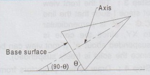
Engineering Graphics: Unit III (b): Projections of Solids : Tag: : Engineering Graphics (EG) - Axis Inclined to both the Planes
Related Topics
Related Subjects

Engineering Graphics
GE3251 eg 2nd semester | 2021 Regulation | 2nd Semester Common to all Dept 2021 Regulation