Engineering Graphics: Unit III (b): Projections of Solids
Auxiliary Plane
Engineering Graphics (EG)
Auxiliary plane is an imaginary plane used to draw the projections of surfaces of an object which are not parallel to the three mutually perpendicular planes HP, VP and PP.
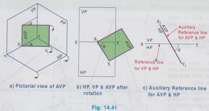
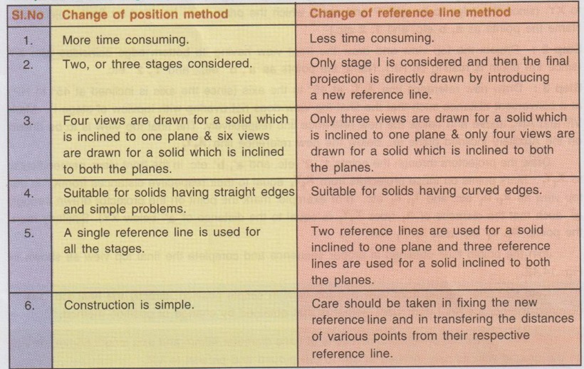
AUXILIARY PLANE Auxiliary plane is an imaginary plane used to draw the projections of surfaces of an object which are not parallel to the three mutually perpendicular planes HP, VP and PP. The imaginary plane which is inclined to HP but perpendicular to VP is called as Auxiliary Inclined Plane, AIP (Fig. 14.40). The intersection of VP and AIP forms a new reference line X1Y1. Similarly the imaginary plane which is inclined to VP but perpendicular to HP is called as Auxiliary vertical plane, AVP (Fig. 14.41). The intersection of HP and AVP forms a new reference line X1Y1. Hence Auxiliary inclined plane (AIP) and Auxiliary vertical plane (AVP) are used to draw the projections of a solid surface on an inclined plane. So far the projections of solids, inclined to one of the planes were drawn by change of position method. These problems can also be solved by Auxiliary plane method. In auxiliary plane method, instead of changing the position of solid after getting views in stage I (ie., Simple position), an auxiliary reference line (ie., a new reference line to represent auxiliary plane) is introduced and then the final projections are directly drawn from the views of stage I. Hence this method is also called as "Change of reference line" method. Note: Both "Change of position method" and "Change of reference line method" can be followed to draw the projections of solids, inclined to one (or) both reference planes and gives the same result. Comparison of "Change of position method" and "Change of reference line method".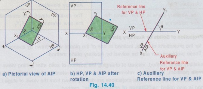
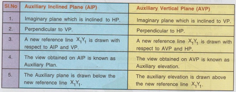
Comparison between AIP and AVP.
1. Projection of Solids by Auxiliary plane method
Engineering Graphics: Unit III (b): Projections of Solids : Tag: : Engineering Graphics (EG) - Auxiliary Plane
Related Topics
Related Subjects

Engineering Graphics
GE3251 eg 2nd semester | 2021 Regulation | 2nd Semester Common to all Dept 2021 Regulation