Engineering Graphics: Unit 0 (c): Lines, Lettering and Dimensioning
Arrangements of Dimensions
Engineering Graphics (EG)
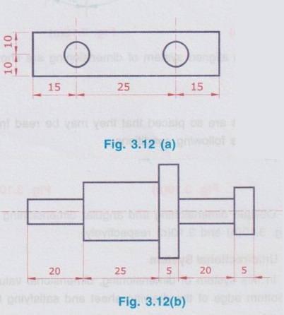
The systems of dimensioning are explained in the previous section, but the dimensions can be arranged in any one of the following ways when the dimensions are in series.
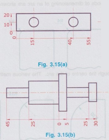
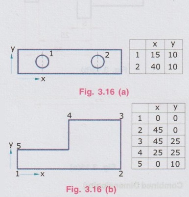
ARRANGEMENTS OF DIMENSIONS The systems of dimensioning are explained in the previous section, but the dimensions can be arranged in any one of the following ways when the dimensions are in series. The selection of the type of arrangement depends on the design and construction requirements. 1. Chain dimensioning 2. Parallel dimensioning 3. Combined dimensioning 4. Progressive dimensioning 5. Dimensioning by co-ordinates In this system, dimensions are arranged in a straight line as shown in Fig.3.12(a) and (b). In this arrangement of dimensioning, all the dimensions are given from a common base line such a way that projection lines and dimension lines do not cross each other by placing the smaller dimensions nearer the view and the larger further away. Parallel dimensioning is shown in Fig. 3.13(a) and (b). In this arrangement of dimensioning both chain dimensioning and parallel dimensioning are combined together as shown in Fig. 3.14(a) and (b). This method is a simplified parallel dimensioning method and is used where there are space limiations to write dimensional values. One datum point or surface is selected which reads as zero and all the dimensions are refered to that point or surface as shown in Fig. 3.15(a) and (b). This type of dimensioning follows the principle of co-ordinate system of identifying the points. A point of origin is selected and the direction of co-ordinate axes are identified, generally keeping the whole drawing in first quadrant (ie., left bottom most edge is normally taken as the reference point). Various points marked in the drawing are identified by its x and y coordinates and tabulated as shown in Fig. 3.16 (a) and (b).1. Chain Dimensioning (or Continuous Dimensioning)
2. Parallel Dimensioning

3. Combined Dimensioning

4. Progressive Dimensioning
5. Dimensioning by Co-ordinates
Engineering Graphics: Unit 0 (c): Lines, Lettering and Dimensioning : Tag: : Engineering Graphics (EG) - Arrangements of Dimensions
Related Topics
Related Subjects

Engineering Graphics
GE3251 eg 2nd semester | 2021 Regulation | 2nd Semester Common to all Dept 2021 Regulation