Basic Electrical and Electronics Engineering: Unit II: Electrical Machines
Applications of DC Generators
These types of DC generators are generally more expensive than self-excited DC generators because of their requirement of separate excitation source.
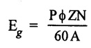
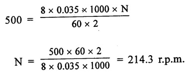
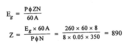
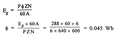
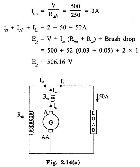
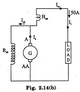
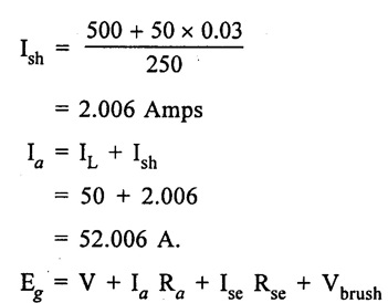
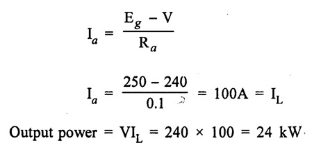
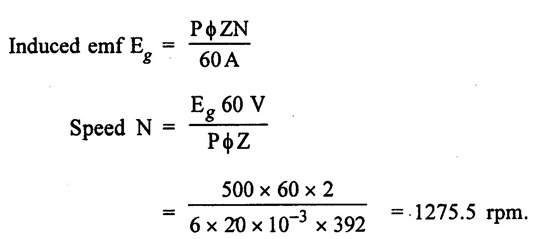
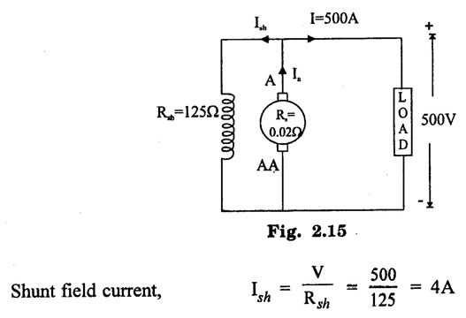
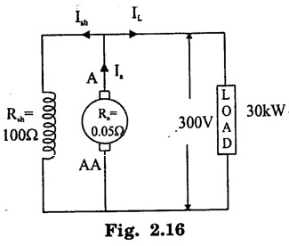
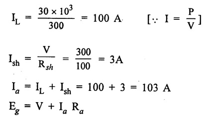
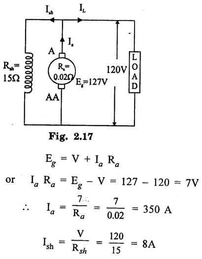
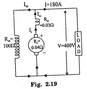
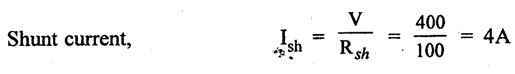
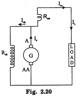
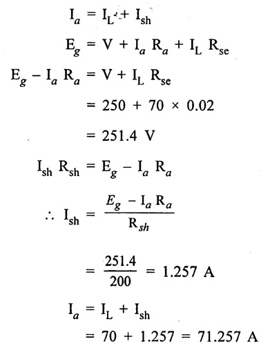
APPLICATIONS OF DC GENERATORS These types of DC generators are generally more expensive than self-excited DC generators because of their requirement of separate excitation source. Because of that their applications are restricted. They are generally used where the use of self-excited generators are unsatisfactory. I. Because of their ability of giving wide range of voltage output, they are generally used for testing purpose in the laboratories. II. Separately excited generators operate in a stable condition with any variation in field excitation. Because of this property they are used as supply source of DC motors, whose speeds are to be controlled for various applications. Example-Ward Leonard Systems of speed control. The application of shunt generators are very much restricted for its dropping voltage characteristic. They are used to supply power to the apparatus situated very close to its position. These type of DC generators generally give constant terminal voltage for small distance operation with the help of field regulators from no load to full load. I. They are used for general lighting. II. They are used to charge battery because they can be made to give constant output voltage. III. They are used for giving the excitation to the alternators. IV. They are also used for small power supply. These types of generators are restricted for the use of power supply because of their increasing terminal voltage characteristic with the increase in load current from no load to full load. We can clearly see this characteristic from the characteristic curve of series wound generator. They give constant electric current in the dropping portion of the characteristic curve. For this property they can be used as constant current source and employed for various applications. I. They are used for supplying field excitation electric current in DC locomotives for regenerative breaking. II. This types of generators are used as boosters to compensate the voltage drop in the feeder in various types of distribution systems such as railway service. III. In series arc lightening this type of generators are mainly used. The compound wound DC generators are most widely used than other types of DC generators, because of its compensating property. I. Cumulative compound wound generators are generally used lighting, power supply purpose and for heavy power services because of their constant voltage property. They are mainly made over compounded. II. Cumulative compound wound generators are also used for driving a motor. III. For small distance operation, such as power supply for hotels, offices, homes and lodges, the flat compounded generators are generally used. IV. The differential compound wound generators, because of their large demagnetization armature reaction, are used for arc welding where huge voltage drop and constant electric current is required. Problem 2.1 A six pole lap wound D.C. generator has 600 conductors, a flux of 40 m.Wb per pole is driven at 400 r.p.m. Find the generated emf. Solution : Number of poles, P = 6 Total number of conductors, Z = 600 Flux per pole, ϕ = 40 m Wb = 40 × 10-3 Wb Speed of rotation, N = 400 r.p.m Number of parallel paths, A = P = 6 [Since the generator is lap wound] Generated e.m.f. Eg: Problem 2.2 A six-pole lap connected generator has a useful flux/pole of 0.045 Wb. If the no load voltage 500 r.p.m. is 300 V, find the conductors on the armature periphery. Solution : Number of poles, P = 6 Useful flux/pole, ϕ = 0.045 Wb No load voltage, Eg = 300 V Number of conductors, Z: Number of parallel paths, A = P = 6 [Since the generator is lap wound] We know that, Hence, total number of armature conductors = 800. Problem 2.3 An 8-pole wave connected D.C. generator has 1000 armature conductors and flux/pole 0.035 Wb. At what speed must it be driven to generate 500 V? Solution : Number of poles P = 8 Total number of armature conductor, Z = 1000 Flux/pole ϕ = 0.035 Wb Generated voltage Eg = 500 V Number of parallel paths, A = 2 [ ⸪ the generator is wave wound] Speed of rotation, N: Using the relation, Hence, speed of generator = 214.3 r.p.m [Ans.] Problem 2.4 An 8-pole, lap wound armature rotated at 350 r.p.m. is required to generate 260 V. The useful flux per pole is 0.05 Wb. If the armature has 120 slots, calculate the number of conductors per slot. Solution : ⸫ Number of conductors / slot = 890/120 = 7.41 This value must be an even number. Hence, conductors/slot = 8 Problem 2.5 The armature of a 6-pole, 600 r.p.m lap-wound generator has 80 slots. If each coil has 4 turns, calculate the flux per pole required to generate an emf of 288 volts. Solution: Each turn has two active conductors and 80 coils are required to fill 80 slots. Z = 80 × 4 x 2 = 640 Problem 2.6 A 4-pole, wave wound generator has 40 slots and 10 conductors are placed per slot. Find, the generated emf when the generator is driven at 1200 rpm and ϕ = 0.02 Wb. Given data : Number of poles P Total number of conductors z = number of slots × conductors per slot z = 40 × 10 = 400 Flux per pole ϕ = 0.02 Wb Speed N = 1200 rpm To find : Generated emf (Eg) Solution: Eg = 320 V [Ans.] Problem 2.7 A compound generator delivers a load current of 50A at 500V. The resistance are Ra 0.05 Ω, Rse = 0.03 Ω and Rsh = 250Ω Find the induced emf if contact drop is 1.0 V per brush. Neglect armature reaction. Assume (a) longshunt, (b) short shunt connection. Solution : Long shunt connection V = 500 V Short shunt connection Now the shunt field current is obtained by dividing (V + IL Rse) by the shunt field resistance = 500 + 52.006 × 0.05 + 50 × 0.03 + 2 Eg = 506.1003 V [Ans.] Problem 2.8 A separately excited generator has induced emf of 250 V and a full load terminal voltage of 240 V. If the value of Ra = 0.1 Ω, find the full load current and output of the generator. Neglect armature reaction and brush drop. Solution: V = 240 V Eg = 250 V Eg = V + Ia Ra P = 24 kW [Ans.] Problem 2.9 A 6 pole, wave wound armature has 49 slots with 8 conductors per slot. Its useful flux per pole is 20 mwb. At what speed, should the armature be rotated in order to obtain an emf of 500 V ? Given data: Number of poles P = 6 For wave wound A = 2 Number of slots = 49 Number of conductors/slot = 8 Useful flux per pole ϕ = 20 mwb Emf Eg = 500 V To find : Number of conductors Z = 49 × 8 = 392 Solution : N = 1275.5 rpm. [Ans.] Problem 2.10 A shunt generator supplied 500 A at 500 V. Calculate its generated emf if its armature and shunt field resistances are 0.02 Ω and 125 Ω respectively. Solution : Load current, I = 500 A Terminal voltage, V = 500 volts Armature resistance, Ra = 0.2 Ω Shunt field resistnce, Rsh = 125 Ω Refer fig. 2.15 Armature current, Ia = I + Ish = 500 + 4 = 504 A Generated emf Eg = V + Ia Ra = 500 + 504 × 0.02 = 510.08 V. Hence generated emf = 510.08 V. [Ans.] Problem 2.11 A 30 kW, 300 V d.c. shunt generator has armature and field resistance of 0.05 Ω and 100 respectively. Calculate the total power developed by the Ω Ω armature when it delivers full load output. Solution : Fig. 2.16 shows the shunt generator circuit. = 300 + 103 × 0.05 = 305.15 V Power developed by armature = Eg Ia = 305.15 × 103 = 31.43 × 10³ W = 31.43 kW. [Ans.] Problem 2.12 A d.c. shunt generator has an induced voltage on open circuit of 127 V. When the machine is on load, the terminal voltage is 120 V. Find the load current if the field resistance be 15 Ω and the armature resistance 0.02 Ω Ignore armature reaction. Solution : Fig. 2.17 shows the conditions of the problem. ⸫ IL = Ia – Ish = 350 – 8 = 342 A [Ans.] Problem 2.13 A series generator delivers a current of 100 A at 250 V. Its armature and series field resistances are 0.1 Ω and 0.055 Ω respectively. Find: (i) Armature current, (ii) Generated emf Solution : Load current I = 100A Terminal voltage, V = 250 Volts Armature resistance, Ra = 0.1 Ω Series field resistance, Rse = 0.055 Ω (i) Armature current, Ia : Armature current (Ia) = load current (I) ⸫ Ia = 100 A [Ans] (ii) Generated emf : Generated e.m.f Eg = V + I (Ra + Rse) = 250 + 100 (0.1 + 0.055) = 265.5 V Hence, generated e.m.f. = 265.5 V [Ans] Problem 2.14 A long shunt compound generator has an armature, series field and shunt field resistances of 0.04 Ω, 0.03 Ω and 100 Ω respectively. It supplies a load current of 180 A at 400 V. Calculate the generated emf. Assume contact drop/ brush = 1 V. Solution: Armature resistance, Ra = 0.04 Ω Series field resistance, Rse = 0.03 Ω Shunt field resistance, Rsh = 100 Ω Load current, I = 180 A Terminal voltage, V = 400 volts Contact drop / brush = 1 V Generated e.m.f. Eg : Armature current, Ia = I + Ish = 180 + 4 = 184 A Generated e.m.f. Eg = V + Ia Ra + Ia Rse + drop at brushes = 400+ 184 × 0.04 + 184 × 0.0 + 2 × 1 = 400 + 7.36 + 5.52 + 2 = 414.88 V Hence, generated emf = 414.88 V [Ans.] Problem 2.15 A short shunt compound dc generator supplies a current of 70 A at voltage 250 V. Calculate the generated voltage if the resistance of armature, shunt field and series field windings are 0.03 Ω, 200 Ω and 0.02 Ω respectively. Solution: Given Ra = 0.03 Rsh = 200 Ω Rse = 0.02 Ω V = 250 Ω IL = 70 A Eg = 250 + (71.257 × 0:03) + (70 × 0.02) = 322.15 V [Ans.]1. Separately Excited DC Generators
Shunt Wound DC Generators
Series Wound DC Generators
Applications of Compound Wound DC Generators
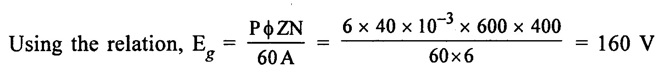 Hence, generated emf Eg = 160 V [Ans.]
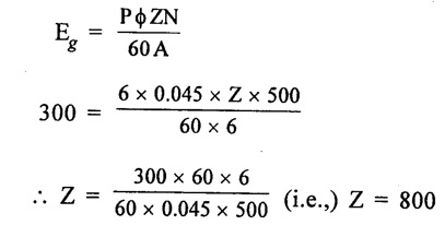

Basic Electrical and Electronics Engineering: Unit II: Electrical Machines : Tag: : - Applications of DC Generators
Related Topics
Related Subjects

Basic Electrical and Electronics Engineering
BE3251 2nd semester Mechanical Dept | 2021 Regulation | 2nd Semester Mechanical Dept 2021 Regulation

Basic Electrical and Electronics Engineering
BE3251 2nd Semester CSE Dept 2021 | Regulation | 2nd Semester CSE Dept 2021 Regulation