Engineering Graphics: Unit V (b): Perspective Projection
Visual Ray Method (Perspective Projection)
Engineering Graphics (EG)
The perspective projection of an object may be drawn by visual ray method by projecting any one set of its orthographic projections.
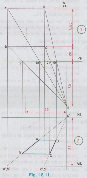
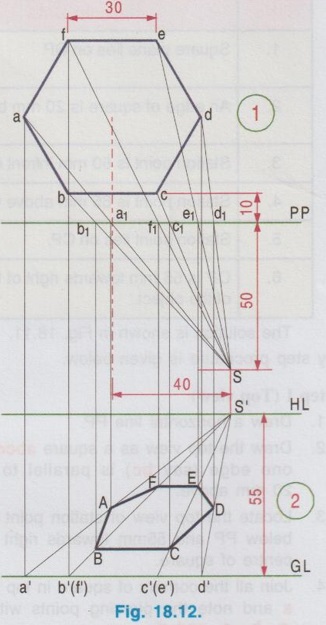
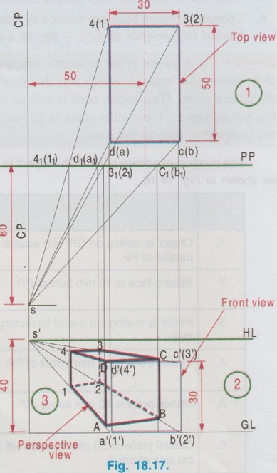
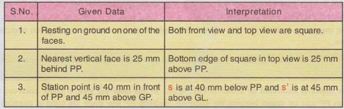
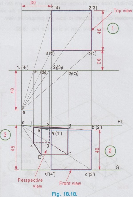
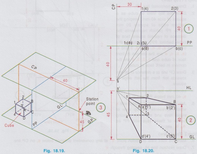
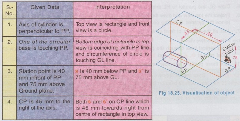
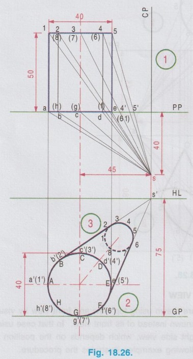
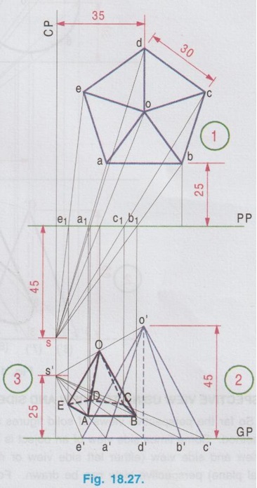
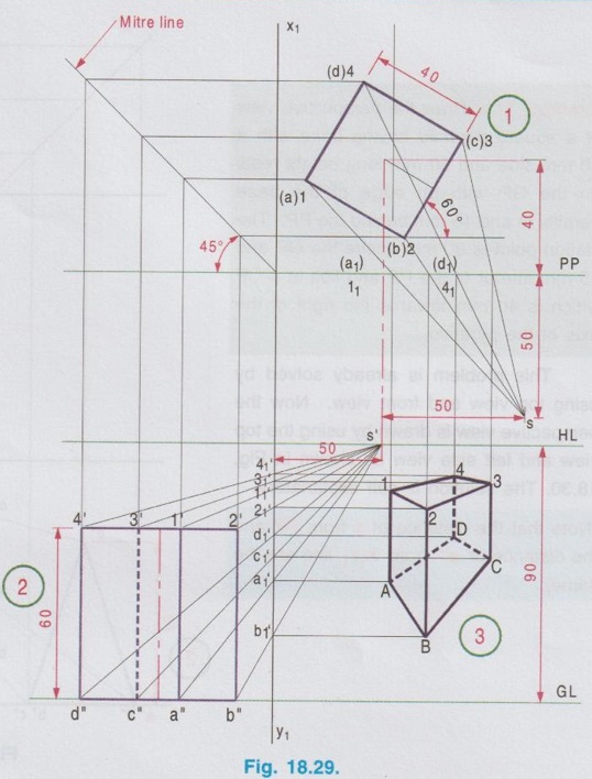
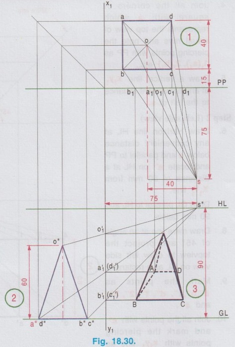
VISUAL RAY METHOD The perspective projection of an object may be drawn by visual ray method by projecting any one set of its orthographic projections. i) Top view and Front view, (or) ii) Top view and Side view. (i) If Top view and Front view are known 1. Draw the layout of perspective projection consisting PP, GL, HL, CP and station point SP (ie., location of s and s') as explained in article 18.9. 2. Draw the visual rays of all the points in top view joining the top view of station point s and note the intercepts of each line with PP line. 3. Similarly draw the visual rays of all the points in front view joining the front view of station point s'. 4. Draw vertical projectors from each intercepts of visual rays of top view made with picture plane PP, till it meets the visual rays of corresponding points in front view joined with s'. The point of intersection is taken as the perspective view of that particular point. 5. Similarly obtain the perspective view of other points of the object. 6. Join the perspective view of all the points in proper sequence to get the perspective view of the object. (ii) If Top view and Side view are known 1. Draw the layout of perspective projection as explained in article 18.9. 2. Draw the top view above PP and side view above GL. 3. Locate the top view and front view of the station point (ie., s and s'). 4. Draw the central plane CP and edge of PP (ie. PP side). 5. Draw the visual rays of all the points in top view joining s and note the intercepts made with PP and then draw the vertical projectors through the intercepts. 6. Similarly draw the visual rays of all the points in side view joining s' and note the intercepts made with PP side and then draw the horizontal projectors through the intercepts to meet the vertical projectors as explained in the previous step. 7. Let the point of intersection of vertical projector from PP and corresponding horizontal projector from PP side be the perspective view of that particular point. 8. Similarly obtain the perspective view of all the points. 9. Join the perspective view of all the points in a proper sequence to get the perspective view of the object. 1. Perspective Projection of Lines by Visual Ray Method Example 1: A straight line AB of 60 mm long is parallel to and 10 mm above the ground plane and inclined at 45° to PP with one end 20 mm behind the picture plane. The station point is 35 mm infront of the picture plane and 45 mm above the ground plane and lies in a central plane that passes through the midpoint of AB. Draw the perspective view of the line. Step 1: (Top view) 1. Draw the picture plane (PP) line and draw the top view of the line AB as ab, such that the end a is 20 mm above PP and ab = 60 mm, inclined at 45° to PP. 2. Draw the central plane (CP). It is given that the central plane is passing through the mid point of AB. Hence locate the midpoint of ab and erect a vertical line through the point to represent CP. 3. Along the CP line mark the station point s, 35 mm below PP. 4. Join the points a and b with s to represent the top view of the visual rays, and mark the piercing points of these visual rays with PP line as a1 and b1 respectively. Step 2: (Perspective view) 5. At any convenient distance below the top view of station point s, locate the front view of station point s' on CP line. 6. Draw a horizontal line through s' to represent Horizon line (HL). 7. Draw the Ground Plane line (GL) parallel to HL and 45 mm below HL. 8. Project the top view and draw the front view of the line as a'b', parallel to GL and 10 mm above GL. 9. Join the points a' and b' with s'. 10. Draw vertical lines through a1 and b1 to cut the lines s'a' and s'b' at A and B respectively. (Note that s'a' and s'b' are the front view of the visual rays). 11. Join the points A and B with thick continuous line which is the required perspective view of the line AB. 2. Perspective Projection of Plane Figures by Visual Ray Method Example 2: Draw the perspective projection of a square lamina of 40 mm side lies on the ground plane such that one of its corners is touching the PP and an edge is inclined at 60° to PP. The station point is 40 mm infront of PP, 60 mm above GP and lies in a central plane which is at a distance of 35 mm to the right of the corner touching the PP. Step 1: (Top view) 1. Draw the picture plane line PP. 2. Draw the top view of the lamina as a square of 40 mm side such that a corner (say b) is touching PP and an edge (say bc) is inclined at 60° to PP. 3. It is given that the central plane lies at a distance of 35 mm to the right of corner touching PP (ie. the corner b). Hence locate the point s, at 35 mm on the right side of b and 40 mm below PP line. 4. Join the top view of station point s with all the four corners of the square lamina and note the points of intersection with PP line as a1, b1, c1 and d1 respectively. Step 2: (Perspective view) 5. At any convenient distance draw Horizon line (HL), parallel to PP. 6. Draw vertical line through s (ie. CP line) to intersect HL at s' which is the front view of station point. 7. Draw Ground line (GL) parallel to HL and 60 mm below. 8. Project the top view and draw the front view of lamina as a straight line a'd'b'c' lies on GL. 9. Join s' with a', b', c' and (d'). 10. Erect a vertical line through the point a1 to meet the line a' s' at A. 11. Similarly obtain the points B, C and D. 12. Join the points A, B, C and D in a proper sequence, which is the required perspective view. Note: The given data in the problem are interpreted in the solution shown in Fig. 18.10 as tabulated below. Similarly the given data in the following problems may be interpreted. Example 3 : A Square plane of 50 mm side lies on GP with an edge parallel to and 20 mm behind the PP. The station point is 60 mm infront of PP, 65 mm above GP and lies in a CP which is 55 mm towards right of the centre of the object. Draw its perspective view. The solution is shown in Fig. 18.11. The step by step procedure is given below. Step 1 (Top view) 1. Draw a horizontal line PP. 2. Draw the top view as a square abcd keeping one edge (say bc) is parallel to PP and 20 mm above. 3. Locate the top view of station point s, 60mm atb below PP and 55mm towards right from the centre of square. 4. Join all the corners of square in top view with s and note the piercing points with PP as a1, b1, c1, and d1. Step 2 (Perspective View) 5. Draw Horizon Line (HL), at any convenient distance below s and parallel to PP. 6. Project the point s to HL to obtain s'. 7. Draw the Ground line, parallel to HL and 65 mm below. 8. Project the top view to GL and draw the front view b'(a)- c'(d') as a straight line. 9. Join the points b'(a') and c'(d') with s'. 10. Project the points a1, b1, c1, and d1 by drawing vertical lines to meet corresponding lines a's', b's', c's' and d's' at A, B, C and D respectively. 11. Join the points A, B, C and D in proper sequence which is the required perspective view. Example 3A: Draw the perspective view of a hexagonal plane of 30 mm side which lies on GP with an edge parallel to and 10 mm behind the PP. The station point is 50 mm infront of PP, 55 mm above GP and lies in a CP which is at a distance of 40 mm towards right of the centre of the object. Step 1 (Top view): 1. Draw a horizontal line PP. 2. Draw the top view of hexagon of side 30 mm above PP line such that an edge is parallel to and 10 mm above PP line. 3. Locate the top view of station point s 50 mm below PP line and 40 mm to the right of centre of hexagon. 4. Join all the corners of hexagon with s and note the piercing points of these visual rays with PP line. Let the piercing points be a1, b1, c1 etc. 5. At a convenient distance draw Horizontal line HL parallel to PP line. 6. Project s to HL and locate s' on HL. 7. Draw Ground line GL at a distance of 55 mm below HL and parallel to HL. 8. Project the top view and draw the front view of hexagon as a straight line, which lies on GL. Note the points on front view as a', b', c' etc., Step 2 (Perspective View) 9. Join s' with a', b', c' etc., which represents the front tones view of visual rays. 10. Erect vertical lines through a1, b1, c1 etc. to intersect the lines s'a', s'b', s'c' etc. respectively at A, B, C etc. 11. Join the points A, B, C etc. in proper sequence which is the required perspective view. Example 4: Draw the perspective view of a circular plane with a 50 mm diameter placed on GP with its centre at a distance of 40 mm behind PP. The station point is 55 mm infront of the PP, 75 mm above GP and lies in the CP which is 35 mm to the right of the centre of the circle. Perspective projection is shown in Fig. 18.13. Step 1 (Top view) 1. Draw the PP line horizontally. 2. Draw the top view of plane as a circle of diameter 50 mm such that its centre point is 40 mm above PP. 3. Divide the circumference of circle into eight equal parts and name the parts as a, b, c, d etc. 4. Locate the top view of station point s such that it is at a distance of 55 mm below PP line and 35 mm to the right of centre of circle. 5. Join the points a, b, c, d etc. with s which represents the top view of visual rays and locate the piercing points a1, b1, c1, d1etc. with PP line. Step 2 (Perspective view) 6. Draw horizon line HL parallel to and at any convenient distance from PP. 7. Project s and locate s' on HL. 8. Draw Ground line parallel to and 75 mm below HL. 9. Project the top view and draw the front view as a straight line which lies on GL. Mark the points on front view as a', b', c' etc. 10. Join the points a', b', c' etc. with s which represents the front view of visual rays. 11. Erect vertical lines through the points a1, b1, c1 etc. (ie., the piercing points of visual rays with PP line) to intersect the lines s'a', s'b', s'c' etc respectively at A, B, C etc. 12. Join the points A, B, C etc. in proper sequence which is the required perspective view. Example 5: A circular plate of 60 mm diameter is resting on one of the points of its rim on the ground plane (GP). It is parallel to and 25 mm behind the picture plane for the perspective projection. The station point is 60 mm in front of the PP and 90 mm above GP. Draw the perspective projection of the centre if the CP is 10 mm to the left of the centre of the circular plate. Perspective projection is shown in Fig. 18.14. Note: It is given that the circular plate is resting on one of the points of its rim on ground. Hence draw the front view as a circle on GL. Step 1 (Front view) 1. Draw a horizontal line GL. 2. Draw the front view of the plate as a circle of diameter 60 mm such that it is resting on one of the points of its rim on GL. 3. Divide the circumference of circle into 8 equal parts and name the points as a', b', c' etc. 4. Draw Horizon line HL parallel to and 90 mm above GL. 5. Locate the front view of station point s' on HL such that s' is at a distance of 10 mm to the left of centre of circle. 6. Join the points a', b', c' etc. with s' which represents the front view of visual rays. Step 2 (Top View) 7. Draw vertical line through s' to represent CP. 8. Locate the point s on CP at a convenient height from s'. 9. Draw horizontal line PP at a distance of 60 mm above s. 10. Project the circle from front view to top view as a straight line, parallel to PP and at a distance of 25 mm above PP. Name the points in top view as a, b, c etc., 11. Join the points a, b, c etc with s and locate the points of intersection of these lines with PP as a1, b1, c1 etc. Step 3 (Perspective View) 12. Erect vertical lines through the points a1, b1, c1 etc. to intersect the lines s'a', s'b', s'c' etc. at A, B, C etc. 13. Join the points A, B, C etc. in a proper sequence which is the required perspective view. Example 6: Draw the perspective view of a rectangular lamina of size 50 mm x 30 mm which rests on the ground with the longer edge on PP. The station point is 50 mm above Ground plane and 25 mm infront of PP and lies on a central plane 35 mm to the left of the nearest edge of the lamina. The perspective view is shown in Fig. 18.15. 3. Perspective Projection of Solid figures by Visual Ray Method Case (a): (Parallel (or) one point perspective) Perspective view using Top view and Front view In the previous article the procedure of drawing perspective view of a plane figure was explained. For a plane figure, placed on a ground plane, top view is a plane figure but front view is a straight line. Whereas while drawing perspective view of a solid figure, placed on a ground plane, both top view and front view are plane figures. Hence draw the top view and front view for the given position of solid and locate the top view and front view of station point. Follow the same procedure as explained for a plane figure and draw the perspective view. Note: 1. Top view and perspective view are drawn using thicklines while front view and all the remaining lines are drawn using thin lines. 2. Corners of perspective views are marked with capital letters. 3. Perspective views are not normally dimensioned. 4. Corners at bottom base are marked by letters A, B, C etc. where as the corners at top base are marked by numerals as 1, 2, 3 etc. as explained in projection of solids. Example 7: A square prism of 30 mm side and 50 mm length is kept on the ground plane on one of its rectangular faces in such a way that one of its square faces is parallel to and 10 mm behind the picture plane. The station point is located 60 mm infront of the picture plane and 40 mm above the ground plane. The central plane is 50 mm away from the axis of the prism towards left. Draw the perspective view of the prism. The position of square prism with respect to the ground plane and picture plane may be visualised as shown in Fig. 18.16. The perspective view is shown in Fig. 18.17. and the procedure of drawing perspective view is explained below. Step 1 (Top view) 1. Draw a horizontal line PP. 2. Draw the top view of prism as a rectangle of size 30 mm × 50 mm, keeping 30 mm side parallel to PP and 10 mm above PP. 3. Mark the corners as d(a), c(b), 4(1) and 3(2). 4. Locate the top view of station point s, 60mm below PP line and 50 mm towards left from the centre of rectangle. 5. Join all the corners of rectangle with s and note the piercing points with PP as d1(a1), c1 (b1), 41 (11) and 31 (21). Step 2 (Front view) 6. Draw horizon line HL at any convenient distance from s and parallel to PP. 7. Project s and locate s' on HL. 8. Project the top view and draw the front view above GL as a square. 9. Mark the corners as a'(1'), b'(2), c'(3') and d'(4'). 10. Join all the corners with s'. Step 3 (Perspective View) 11. Erect vertical lines through the piercing points of visual rays with PP a1, b1, 11, 21 etc. to intersect the front view visual rays of corresponding points. 12. Mark the points of intersection as A, B, C, D, 1, 2, 3 and 4. 13. Join these points in a proper sequence which is the required perspective view. Note: Examination point of view the visualisation of object shown in Fig. 18.16. is not to be drawn. It may be developed as a freehand sketch for better understanding. Example 8: A cube of side 40 mm is resting on the ground on one of the faces in such a way that the nearest vertical face is parallel to and 20 mm behind PP. The central plane is located 30 mm to the left of the nearest face of the cube. The station point is 40 mm infront of PP and 45 mm above GP. Draw the perspective view of the solid. The perspective view is shown in Fig. 18.18 and the step by step procedure of drawing the perspective view is given below. Step 1 (Top view) 1. Draw a horizontal line PP. 2. Draw the top view of cube as a square of side 40 mm, keeping the bottom edge of square 20 mm above PP (which represents the distance of nearest square face of 99 cube behind PP) and name the corner as a, b, c, d, 1, 2, 3 and 4. (a, b, c, d are the corners in front face of cube and 1, 2, 3, 4 are the corners in back face of cube) 3. Draw CP line at a distance of 30 mm towards left from the left edge of square. 4. Locate the top view of station point s, 40 mm below PP on CP line. 5. Join all the corners of square with s which represents the top view of visual rays and mark the piercing points of these rays with PP as a1, b1 etc. Step 2 (Front view) 6. Mark the front view of station point s' at any convenient distance below s, on CP line. 7. Draw Horizon line HL passing through s'. 8. Draw Ground line GL parallel to and 45 mm below HL. 9. Project the top view and draw the front view as a square of side 50 mm such that the bottom edge coincides with GL. Name the points in front view as 1',2',3',4', a',b', c' and d'. 10. Join all the corners with s' which represents the front view of visual rays. Step 3 (Perspective View) 11. Erect vertical lines through the piercing points of visual rays with PP (ie., a1, b1, 11, 21 etc.) to intersect the front view of visual rays (ie., a's', 1's', b's', 2's' etc.) at A, 1, B, 2 etc., 12. Join the points A, B, C, D, 1, 2, 3 and 4 in proper sequence which is the required perspective view. Example 9: In the above problem if the vertical face of cube is touching PP, draw the perspective view. The object is visualised as shown in Fig. 18.19. In this case top view of cube, observed as a square on PP can be drawn keeping the edge AB touching PP line since the cube is touching PP. Similarly front view of cube, observed as a square can be drawn keeping the edge DC touching GL line since the cube is resting on GP. Otherwise the same procedure as explained in the previous problem can be followed to draw the perspective view. The perspective view is shown in Fig. 18.20. Example 10: Draw the perspective view of a square prism having base with a 40 mm side and 60 mm long axis resting on its base in the GP with its axis 40 mm behind PP and a vertical face right to the axis inclined at 60° to it. The station point is 50 mm in front of PP, 90 mm above GP and lies in a CP which is 50 mm towards right of the axis. The object is visualised with respect to PP, GP and AGP as shown in Fig. 18.21. (Free hand sketch can be developed if required, for better understandings. The perspective view of the prism is shown in Fig. 18.22. The step by step procedure of drawing perspective view is given below : Step 1 (Top view) 1. Draw the top view as a square of side 40 mm, keeping right side is inclined at 60° to horizontal and draw horizontal PP line keeping the centre of square at 40 mm above PP. 2. Locate s 50 mm below PP and 50 mm right from the centre of square in top view and join all the corners of square in top view. 3. Mark the piercing points of visual rays with PP line. Step 2 (Front view) 4. Locate s' on HL at any convenient distance below s. 5. Project the top view and draw the front view. 6. Join all the corners of front view with s'. Step 3 (Perspective View) 7. Erect vertical lines through the piercing points of visual rays with PP to meet the front view of visual rays at A, B, C, D & 1, 2, 3, 4. 8. Join these points in proper sequence which is the required perspective view. Example 11: Draw the perspective view of a square pyramid having base with a 40 mm side and 60 mm long height rests on the GP with an edge of the base parallel to and 15 mm behind the PP. The station point is 80 mm above the GP and 75 mm infront of the PP and lies in a CP which is 40 mm towards the right of the axis of the pyramid. The Perspective projection is shown in Fig. 18.23. Step 1 (Top view) 1. Draw horizontal line PP. Draw top view as a square of side 40 mm keeping the bottom edge, 15 mm above PP. 2. Locate s, 75 mm below PP and 40 mm on the right side of centre of square. 3. Join all the corners of square with s and note the piercing points with PP. Step 2 (Front view) 4. Draw HL line at any convenient distance and project s to s'. 5. Draw GL line parallel to HL and 80 mm below. 6. Project the top view and draw the front view as a triangle, keeping the base touching the GL line (since the pyramid is resting on GP on its base) 7. Join all the corners of front view with s'. Step 3 (Perspective view) 8. Erect vertical lines through the piercing points of visual rays with PP to meet the front view of visual rays at O, A, B, C and D. 10. Join these points in a proper sequence which is the required perspective view. Example 12: Draw the perspective view of a rectangular pyramid of base 35 mm x 25 mm and height 35 mm rests with its base on the ground such that one of the longer base edges is in PP and the rest behind it. The station point is 40 mm infront of PP, 50 mm above the ground and 35 mm to the left of the axis of the pyramid. The perspective view is shown in Fig. 18.24. Example 13: Draw the perspective view of a cylinder of diameter 40 mm and height 50 mm resting on the ground with its axis perpendicular to the PP and one of its circular base touching the picture plane. The station point is 45 mm to the right of the axis of the cylinder, 40 mm infront of PP and 75 mm above Ground plane. The object may be visualised with respect to PP, GP and AGP as shown in Fig. 18.25. Given datas are interpreted as below: The perspective view is shown in Fig. 18.26 and the step by step procedure of drawing perspective view is given below. Step 1 (Top view) 1. Draw a horizontal line PP. Draw the top view as a rectangle of base 40 mm and height 50 mm, keeping the bottom base coincides with PP. 2. Draw CP line, 45 mm towards right from the centre of rectangle. 3. Mark s at 40 mm below PP. 4. Join all the corners of rectangle with s and mark the piercing points with PP. Step 2 (Front view) 5. Locate s' on CP line at any convenient distance from s. 6. Draw Horizon line passing through s' and parallel to PP. 7. Draw GL, parallel to HL and 75 mm below. 8. Project the top view and draw the front view as a circle above GL. Divide the circumference of circle into 8 equal parts and name the parts as a', b', c' etc., 9. Project the divisions to the top view and name the parts as a, b, c etc. at the bottom base and 1, 2, 3 etc. at the top base of rectangle. Step 3 (Perspective view) 10. Join the points a, b, c etc. and 1, 2, 3 etc. with and note the piercing points with PP line as a1, b1, c1 etc. and 11, 21, 31 etc., 11. Erect vertical lines through these piercing points a1, b1, 11, 21 etc. to meet the lines joined by the points a', b', 1', 2' etc., with s' at A, B, 1, 2, etc., 12. Join the points A, B, 1, 2 etc., in proper sequence which is the required perspective view. Example 14: A pentagonal pyramid of 30 mm base side and axis height 45 mm is resting on its base on the ground with a base side parallel to and 25 mm behind PP. The central plane is 35 mm to the left of the apex and the station point is 45 mm infront of PP and 25 mm above the ground plane. Draw the perspective view of the pyramid. The perspective view of the pentagonal pyramid is shown in Fig. 18.27. Example 15: Draw the perspective projection of a cone of base diameter 50 mm and axis height 65 mm resting on ground with its base, axis being 30 mm behind PP. The station point is 55 mm to the right of the vertex of cone, 45 mm in front of PP and 80 mm above GP. The perspective view is shown in Fig. 18.28. PERSPECTIVE VIEW USING TOP VIEW AND SIDE VIEW So far the perspective views of solid figures are drawn using top view and front view by visual ray method. Some times side view of an object is known instead of its front view. In that case using top view and side view (either left side view or right side view, which depends on the position of central plane) perspective view can be drawn. Following examples illustrates the procedure. Example 16: Draw the perspective view of a square prism having base with a 40 mm side and 60 mm long axis resting on its base in the GP with its axis 40 mm behind PP and a vertical face right to the axis inclined at 60° to it. The station point is 50 mm infront of PP, 90 mm above GP and lies in a CP which is 50 mm towards right of the axis. This problem is already solved by using top view and front view. (Refer Example 10) Now the perspective view will be drawn by using top view and left side view as explained below : Step 1 (Top view) 1. Draw a horizontal line PP. Draw the top view as a square of side 40 mm keeping right side edge is inclined at 60° to PP and centre of square is at 40 mm above PP. 2. Name the corners as 1(a), 2(b), 3(c) and 4(d). 3. Locate s at 50 mm towards right from the centre of square and 50 mm below PP. 4. Join all the corners of square with s which represents the top view of visual rays and note the piercing points with PP as 11(a1), 21 (b1) etc., 5. Draw a vertical line x1y1 at any convenient distance to the left of s. Step 2 (Left side view) 6. Draw Horizon line HL at any convenient distance below s and parallel to PP and locate s" on HL at a distance of 50 mm from X1Y1 line. 7. Draw GL parallel to HL and 90 mm below. 8. Draw mitre line at an angle of 45° and project the topview to draw left side view on GL as a rectangle. 9. Mark the points as a", b", c", d", 1", 2", 3′′ and 4". 10. Join all the points with s" and mark the piercing points with x1y1 line as a1', b1', 11', 21' etc., Step 3 (Perspective View) 11. Erect a vertical line through the point a1 (ie. piercing point of as with PP) to intersect a horizontal line drawn through a1' (ie. piercing point of a"s" with x1y1 line) at A. 12. Similarly obtain the other points B, C, D, 1, 2, 3 and 4. Join these points in a proper sequence which is the required perspective view. Note : 1. Note that the perspective view is similar to the one obtained in example 10, drawn by using top view and front view. 2. If side view of an object is simple than its front view, this method may be adopted. 3. If not specified in the problem, any convenient method may be followed. 4. Distance of s from PP and distance of s" from x1y1 line are the same. 5. Overlapping of front view on perspective view could be avoided in this method. Example 17: Draw the perspective view of a square pyramid having base with a 40 mm side and 60 mm long height rests on the GP with an edge of the base parallel to and 15 mm behind the PP. The station point is 90 mm above the GP and 75 mm infront of the PP and lies in a CP which is 40 mm towards the right of the axis of the pyramid. This problem is already solved by using top view and front view. Now the perspective view is drawn by using the top view and left side view as shown in Fig. 18.30. The solution is self explanatory. (Note that the distance of s from PP and the distance of s" from x1y1 line are the same). Example 18: Draw the perspective view of frustum of a square pyramid with a 50 mm base edge, 25 mm top edge and 45 mm height rests on its base in the GP with an edge of the base parallel to and 20 mm behind the PP. The station point is 75 mm above the GP and 55 mm infront of the PP and lies in a CP which is 40 mm towards the right of the axis. The perspective view is obtained by using topview and front view as shown in Fig. 18.31. The perspective view of the same object obtained by using topview and side view is shown in Fig. 18.32. (Note that the perspective view is similar by both the methods). Case (b): Angular (or) Two Point Perspective So far the parallel (or) one point perspective view of solid figures are drawn in which the front face of the perspective coincides with PP. Now the angular (or) two point perspective method of drawing solid figures by visual ray method is explained in this section. In angular perspective projection, two principal faces, (Front face and one side face) of the object are kept at an angle, usually 30° or 60° to PP. The steps generally followed to draw angular perspective view are: 1. Draw the top view above PP such that one face of the object is at 60° to PP. 2. Locate s and Join all the corners in topview with s. Draw vertical lines through the piercing points of these lines with PP. 3. Draw HL and GL. 4. Project the topview and draw front view. 5. Locate s' and Join all the corners in front view with s'. 6. Mark the points of intersection of vertical lines drawn through the piercing points with PP to meet the front view of visual rays of respective points. 7. Join the points in proper sequence and obtain the perspective view. Note : 1. Unless specified in the problem, any method, either parallel perspective (or) angular perspective can be drawn. 2. if side view is known instead of front view draw the topview at an angle of 60° with PP. The same procedure can then be followed as explained for parallel perspective. Example 19: Draw the perspective view of a rectangular prism of 80 mm x 40 mm x 35 mm lying on its 80 mm x 40 mm rectangular face on the ground plane with a vertical edge touching the picture plane and the end faces inclined at 60° with the picture plane. The station point is 90 mm infront of the picture plane, 70 mm above the ground plane and it lies in a central plane with axis through the centre of the prism. Step 1 (Top view) 1. Draw a horizontal line PP. 2. Draw the top view as a rectangle keeping the side of base inclined at 60° to PP. 3. Locate the centre of rectangle and draw a vertical line through it which represents the CP. 4. Locate s on CP at a distance of 90 mm below PP. 5. Join all the corners of rectangle with s and mark the piercing points with PP as a1, b1, 11, 21 etc., Step 2 (Front view) 6. Draw Horizon line HL at any convenient distance below s and project s on HL as s'. 7. Draw GL parallel to HL and 70 mm below. 8. Project the topview and draw the front view as a rectangle. 9. Join all the corners of rectangle in front view with s' which represents the front view of visual rays. Step 3 (Perspective view) 10. Erect vertical lines through the piercing points of visual rays with PP to meet the front view of visual rays at A, B, C, D, 1, 2, 3 and 4. 11. Join these points in a proper sequence which is the required perspective view.


Engineering Graphics: Unit V (b): Perspective Projection : Tag: : Engineering Graphics (EG) - Visual Ray Method (Perspective Projection)
Related Topics
Related Subjects

Engineering Graphics
GE3251 eg 2nd semester | 2021 Regulation | 2nd Semester Common to all Dept 2021 Regulation