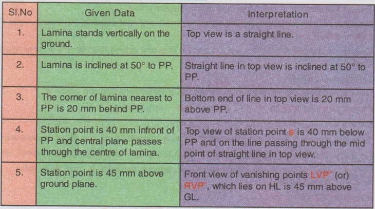
Engineering Graphics: Unit V (b): Perspective Projection
Vanishing Point Method (Perspective Projection)
Engineering Graphics (EG)
So far the perspective view of objects are drawn by visual ray method.
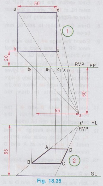
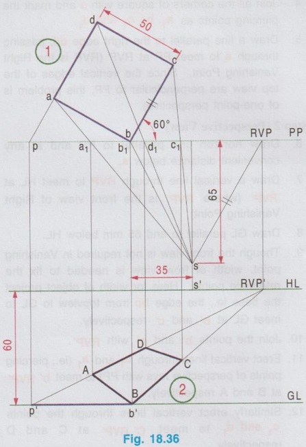
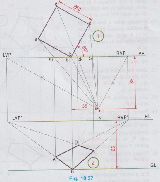
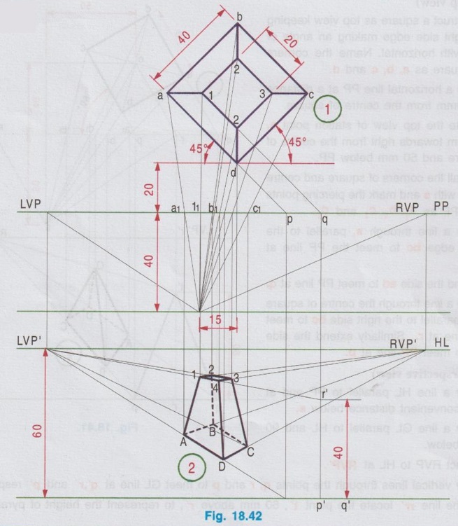
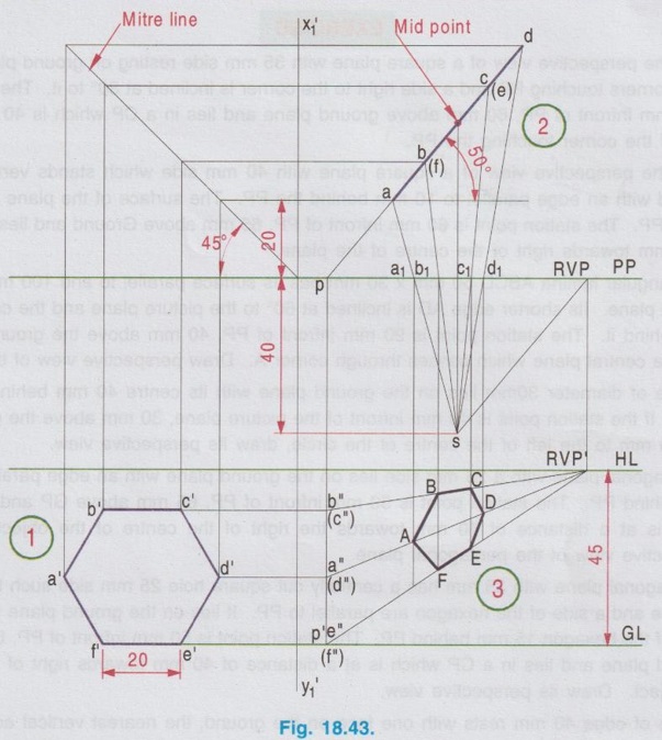
VANISHING POINT METHOD So far the perspective view of objects are drawn by visual ray method. In visual ray method, the station point is located first and then the points forming the perspective view are obtained by drawing visual rays from the station point (also called as the point of sight) to both the top view and front view of the object. In vanishing point method, the vanishing point (or vanishing points) are to be located initially. Vanishing points are the imaginary points located at infinite distance from the observer and they exist on the horizon line. Consider two rails along with the platforms and adjacent electric posts, observed by an observer, assuming the observer is stationed in between the two rails of a track. The photography ie., perspective view of the arrangement (Railway track with adjacent electric post) will be obtained as shown in Fig. 18.34. In Fig. 18.34, the imaginary point at infinite distance away from the station point at which the image of the object converge is known as vanishing point, marked as `VP' in fig. It is noted from Fig. 18.34 that the vanishing point will appear to lie at eye level (Horizon line) ie., at the point where the original image of the object vanishes. The overhead electric cable also appears to meet at the same vanishing point. Location of Vanishing Point In actual the vanishing point is an imaginary point at infinite away from the observer and hence cannot be located on a plain paper. But in practice, it is marked in perspective drawing as a point at which the visual ray from the eye piercing the picture plane (PP). To draw the perspective view of any object by vanishing point method, two vanishing points LVP and RVP are to be located first. where LVP = Left Vanishing Point and RVP = Right Vanishing Point After locating LVP and RVP on PP line, these points are to be projected to HL line to mark their respective front views LVP' and RVP', where LVP' = Front View of Left Vanishing Point, and RVP' = Front View of Right Vanishing Point (Both LVP' and RVP' lies on HL line) To locate LVP and RVP 1. Draw the topview of the object and locate the topview of station point s according to the given condition. 2. Through s draw a line parallel to the left edge of the object to intersect PP line at LVP. 3. Similarly through s draw a line parallel to the right edge of the object to intersect PP line at RVP. To locate LVP' and RVP' 1. Through LVP draw a vertical line to intersect HL at LVP'. 2. Similarly through RVP draw a vertical line to intersect HL at RVP'. After locating LVP' and RVP', perspective view of an object can be easily drawn. Following examples illustrates the procedure of drawing perspective view by vanishing point method. Note: 1. If left edge (or) right edge of the top view is perpendicular to the PP, then the problem is of one- point perspective. ie., either LVP (or) RVP can be located and the perspective view can be drawn. 2. Similarly if an edge of the base is parallel to PP, the problem is of one point perspective (Refer example 20) 3. Even if both left and right edges of top view are inclined to PP, it can be taken as a one-point perspective (ie. single vanishing point), by locating either LVP or RVP, the perspective view can be drawn (Refer example 21) 4. If both left and right edges are inclined to PP, it can conveniently be taken as a two point perspective (ie., angular perspective), by locating two vanishing points, LVP and RVP and then perspective view can be drawn (Refer Example 22) 5. If not specified in the problem, either visual ray method (or) vanishing point method can be followed. However, vanishing point method normally gives simpler solution. 6. Front view need not be drawn for vanishing point method. However, width of object in front view or height of object in sideview is required to fix the reference points within which the perspective view is drawn. 1. Perspective Projection of Plane Figures by Vanishing Point Method Example 20: A square plane with a 50 mm side lies on GP with an edge parallel to and 20 mm behind the PP. The station point is 60 mm infront of PP, 65 mm above GP and lies in a CP which is 55 mm towards right of the centre of the object. Draw its perspective view. This problem is already solved by Visual Ray Method (Refer Example 3). Now the problem is solved by Vanishing Point Method. Step 1 (Topview) 1. Draw a horizontal line PP. 2. Draw the top view as a square of side 50 mm and name the corners as a, b, c and d, keeping the base bc 20 mm above PP. 3. Locate the top view of station point s, 60 mm below PP and 55 mm towards right from the centre of square. 4. Join all the corners of square with s and mark the piercing points as a1, b1, c1 and d1. Draw a line parallel to the right edge cd, passing through s to meet PP at RVP (RVP is the Right Vanishing Point. Since the vertical edges of the top view are perpendicular to PP, this problem is of one-point perspective). Step 2 (Perspective View) 6. Draw horizon line parallel to PP and at any convenient distance below s. 7. Draw a vertical line through RVP to meet HL at RVP' (where RVP' is the front view of Right Vanishing Point) 8. Draw GL parallel to and 65 mm below HL. 9. Though the front view is not required in Vanishing point, width of front view is needed to fix the reference points. Here for width of object project the base ie., the edge bc from topview to GL to meet GL at b' and c' respectively. 10. Join the points b' and c' with RVP'. 11. Erect vertical lines through b1 and a1 (ie., piercing points of perspective rays with PP) to meet b' RVP' at B and A respectively. 12. Similarly erect vertical lines through the points c1 and d1 to meet C' RVP' at C and D respectively. 13. Join the points A, B, C and D in a proper sequence which is the required perspective view. Example 21: Draw a perspective view of a square plane with a 50 mm side resting on the GP with one of its corners touching PP and a side right to the corner inclined at 60° to it. The station point is 65 mm infront of PP, 60 mm above GP and lies in a CP which is 35 mm towards right of the corner touching the PP. Step 1 (Top view) 1. Draw a horizontal line PP. 2. Draw the topview as a square keeping one of the corner (say b) touching PP and right side edge (bc) inclined at 60° to PP. 3. Locate the topview of station point s, 65 mm below PP and 35 mm towards right from the corner touching PP (ie., b). 4. Join all the corners of square with s and mark the piercing points with PP as a1, b1, c1 and d1. 5. Draw a line passing through s and parallel to right edge bc to meet PP at RVP. Step 2 (Perspective view) 6. Draw horizon line HL parallel to PP and at any convenient distance below s. 7. Erect vertical line through RVP to meet HL at RVP', which is the front view of Right Vanishing Point. 8. Draw GL parallel to and 60 mm below HL. 9. Extend the edge ad in top view to meet PP at p and erect a vertical line through p to meet GL at p'. 10. Erect vertical line through b to meet GL at b'. Now the line p' b' gives width of front view of the side at right angles to the edge bc, which are the reference points to draw the perspective view. 11. Join RVP' with p' and b', the boundary within which the perspective view can be drawn. 12. Erect vertical lines through a1 and d1 (ie., piercing points with PP) to meet p' RVP' line at A and D respectively. 13. Similarly erect vertical lines through b1 and c1 to meet b' RVP' line at B and C respectively. 14. Join the points A, B, C and D in a proper sequence which is the required perspective view. Note: 1. Though both left and right edges of topview are inclined to PP, only a single vanishing point (RVP) is located and perspective view is drawn. 2. Instead of RVP, LVP may also be located and perspective view may be drawn. 3. Both LVP and RVP may also be located to draw perspective view, the procedure is explained in example 22. Example 22: Solve the above problem as two point perspective. Step 1 (Top view) 1. Draw a horizontal line PP. 2. Draw the topview as a square and locate s, draw HL and GL as explained in the above example. 3. Join all the corners of square with s and mark the piercing points with PP as a1, b1, c1 and d1. Step 2 (Perspective view) 4. Draw a line through s and parallel to the right edge bc to meet the PP at RVP. 5. Similarly draw a line through s and parallel to left edge ba to meet the PP at LVP. (LVP and RVP are the left and right vanishing points respectively). 6. Draw vertical lines through LVP and RVP to meet HL at LVP' and RVP' (where LVP' and RVP' are the front views of LVP and RVP respectively) 7. The corner b is touching PP, hence draw a vertical line through b to meet GL at B. 8. Joint B with LVP' and RVP'. 9. Draw a vertical line through a1 to meet LVP' B at A. 10. Similarly draw a vertical line through c1 to meet RVP' B at C. 11. Join LVP' and C and RVP' and A. These lines meets at D. (Note that the vertical line drawn through d1 passes through the point D, which is the point of intersection of lines LVP'C and RVP'A) 12. Join the points A, B, C and D in a proper sequence which is the required perspective view. Note: It is suggested to solve the problems as two-point perspective since it gives simpler solution. Example 23: A pentagonal plane with a side of 30 mm is making an angle of 45° with PP is placed on GP with its centre at a distance of 20 mm behind PP. The station point is 70 mm infront of the PP, 65 mm above the GP and lies in a CP which is 50 mm to the right of the centre of the pentagon. Draw its perspective view by vanishing point method. Step 1 (Top view) 1. Construct a pentagon abcde with side bc inclined at 45° to horizontal to represent the top view of the pentagonal plane of side 30 mm. 2. Draw a horizontal line PP at a distance of 20mm from centre of pentagon. 3. Mark the station point s in the given position (70 mm below PP and 50 mm to the right from the centre of pentagon). 4. Join all the corners of pentagon abcde with s and mark the piercing points with PP as a1, b1, c1, d1 and e1 respectively. 5. Draw a line through s and parallel to the right edge bc to meet PP line at RVP. 6. Draw a line HL at convenient distance below PP. 7. Project RVP to HL line at RVP'. Step 2: (Perspective View) 8. Draw a line GL at 65 mm below HL. 9. Draw a line through e in top view, parallel to the right edge bc to meet PP line at p. 10. Similarly draw a line through d (which passes through the point a also) parallel to the right edge bc to meet PP line at q. 11. Let the right edge bc meet the PP line at r. 12. Draw the vertical lines through the points p, q and r to meet GL line at p', q' and r' respectively. 13. Join the points p', q' and r' with RVP'. 14. Project the points b1 and c1 to meet r'RVP' at points B and C respectively. 15. Similarly project the points a1 and d1 to meet q'RVP' at points A and D respectively. 16. Project the points e1 to meet p'RVP' at point E. 17. Join the points A, B, C, D and E in a proper sequence to get the required perspective view. 2. Perspective projection of solid figures by vanishing point method Example 24: A cube of side 40 mm is lying on the ground on one of its faces with the nearest vertical edge, 10 mm behind the PP and the faces equally inclined to PP. The station point is 50 mm in front of PP and 60 mm above the ground plane. The central plane passes through a point 10 mm to the left of the mid of the solid. Draw the perspective view of the solid. Note: This problem is solved as angular perspective. Step 1 (Top view) 1. Draw a horizontal line PP. 2. Construct a square as top view, keeping the bottom corner at 10 mm above PP and both left and right edges at 45° each to PP line. 3. Locate the station point s, such that 50 mm below PP and 10 mm towards left from the centre of square. 4. Join all the corners of square with s and locate the piercing points with PP line. 5. Through the point s draw the lines parallel to the left edge and right edge of the square to meet PP line at LVP and RVP respectively. 6. Extend the side d(h) - a(e) to meet PP line at p. Step 2 (Perspective view) 6. Draw HL line parallel to PP at any convenient distance below the points s. 7. Project the points LVP and RVP to HL line at LVP' and RVP' respectively. 8. Draw a line GL parallel to HL and 60 mm below. 9. Draw a vertical line through the point p to meet GL at p'. 10. On the line pp', locate the point t' such that p't' = 40 mm (equal to thickness of cube). 11. Join the points t' and p' with LVP' and on these lines locate the points D, A and H, E respectively by projecting the intercepts with PP line of the corresponding points vertically. Now DAEH is one of the fully visible front faces (left face). 12. Join the points A and E with RVP' and on these lines get the points B and F by projecting the respective intercepts with PP line vertically. 13. Join the point D with RVP' and the point B with LVP'. Let these two lines meet at C. 14. Now ABFE is one of the fully visible front faces (right face) and ABCD is the visible top face of the cube. 15. Similarly locate the point G by joining H with RVP' and F with LVP'. 16. Join the points in a proper sequence which is the required perspective view. Example 25: A rectangular prism of dimensions 50 mm × 30 mm × 25 mm is lying on the ground in such a way that one of the larger faces is on the ground. A vertical edge is 10 mm behind PP and longer face containing that edge makes 30° inclination with PP. The station point is 60 mm infront of PP, 50 mm above the ground and lies in a central plane which passes through the centre of the prism. Draw the perspective view of the prism by vanishing point method. The perspective view of the prism is shown in Fig. 18.40. Example 26: A square pyramid is having base with a 40 mm side and 60 mm long axis is resting on its base in GL with its axis at a distance of 40 mm behind the PP and an edge of the base right to the axis inclined at 60° to it. The station point is 50 mm infront of PP, 90 mm above GL and lies in a CP which is 50 mm towards the right of the axis. Draw the perspective view of the pyramid by vanishing point method. Note: This problem is solved as One point perspective. Step 1 (Top view) 1. Construct a square as top view keeping its right side edge making an angle of 60° with horizontal. Name the corners of square as a, b, c and d. 2. Draw a horizontal line PP at a distance of 40mm from the centre of square. 3. Locate the top view of station point s, 50 mm towards right from the centre of square and 50 mm below PP. 4. Join all the corners of square and centre point with s and mark the piercing points with PP as a1, b1, c1 and d1. 5. Draw a line through s, parallel to the right edge bc to meet the PP line at RVP. 6. Extend the side ad to meet PP line at q. 7. Draw a line through the centre of square and parallel to the right side bc to meet PP line at r. Similarly extend the side bc to meet PP line at p. Step 2 (Perspective view) 8. Draw a line HL parallel to PP and at any convenient distance below s. 9. Draw a line GL parallel to HL and 90 mm below. 10. Project RVP to HL at RVP'. 11. Draw vertical lines through the points q, r and p to meet GL line at q', r' and p' respectively. 12. On the line rr' locate the point t', 60 mm above r', to represent the height of pyramid. 13. Join the points q', p' and t' with RVP'. 14. Draw the vertical lines through the points b1 and c1 to meet p'RVP' at points B and C respectively. 15. Similarly draw the vertical lines through the points a1, and d1 to meet q'RVP' at points A and D respectively. 16. Project the point O1 to meet t'RVP' at O. 17. Join the points A, B, C, D and O in a proper sequence which is the required perspective view. Example 27: A frustum of a square pyramid of bottom base 40 mm side, top face 20 mm side and height 40 mm is lying on the ground vertically, with its base edges equally inclined to PP. The nearest base corner is 20 mm behind PP. The station point is 40 mm infront of PP and 60 mm above the ground plane and lies in a central plane passing through a point 15 mm to the left of the axis. Draw the perspective projection of the frustum of pyramid by vanishing point method. The problem is solved as two point perspective by locating two vanishing points on left and right of the object. Step 1 (Top view) 1. Draw a horizontal line PP. 2. Construct the top view as two concentric squares of inner square 20 mm side and outer square 40 mm side, with sides equally inclined to PP and keeping the nearest base edge corner 20 mm above PP. 3. Name the corners of outer square as a, b, c and d and name the corners of inner square as 1, 2, 3 and 4 and mark the piercing points with PP as a1, b1, 11, 21 etc., 4. Locate the station point s, 15 mm towards left from the centre of two concentric squares and 40 el meldong en mm below PP. 5. Join all the corners of both inner and outer squares with s. 6. Draw the lines passing through s and parallel to left and right edges of top view to meet PP at LVP and RVP respectively. 7. Extend the side ad of outer square to meet PP at p and extend the side 1-4 of inner square to meet PP at q. Step 2 (Perspective view) 8. Draw a horizonal line HL parallel to PP and at a convenient distance below s. 9. Project LVP and RVP to HL at LVP' and RVP' respectively. 10. Draw a line GL parallel to HL and 60 mm below. 11. Draw the vertical lines through the points p and q to meet GL at p' and q' respectively. 12. On the vertical line qq' locate the point r' such that r' q' = the height of the pyramid, 40 mm. 13. Join p' with LVP' and then erect vertical lines through the point a1 and d1 to meet p'LVP' at A and D respectively. 14. Join A and D with RVP'. 15. Erect vertical line through the point b1 to meet A RVP' line at B. 16. Similarly erect a vertical line through the point c1 to meet D RVP' at C. Now ABCD represents the perspective view of the bottom base of frustum of pyramid. 17. Join the point r' with LVP' and then erect vertical lines through the points 11 and 41 to meet r' LVP' line at 1 and 4 respectively.. 18. Join the points 1 and RVP and erect a vertical line through 21 to meet this line at 2. 19. Similarly join the points 4 and RVP and erect a vertical line through 31 to meet this line at 3. Now 1-2-3-4 represents the perspective view of the top face. 20. Show the invisible edges AB, 2-B, and BC by hidden lines. 21. Join the corners in a proper sequence to get the required perspective view. Note : In top view as 7th step, instead of extending the sides ad and 1-4, the sides 4-3 and d-c can be extended on the left side to mark the points p and q on the left side of top view. And then the other steps can be followed as explained above. 3. Perspective Projection by Vanishing point method using Top view and Side view So far the perspective projection of plane and solid figures are drawn by vanishing point method from the top view of the object and straightaway by marking the height of the object above GL line. But if the top view of an object is a straight line it is advised to draw the side view also (either left side or right side, depends on the location of station point) and then the perspective projection is drawn by using topview and side view. Similarly the top view and side view of a solid figure can be used to draw its perspective view. The following example illustrates this method. Example 28: Draw the perspective view of a hexagonal lamina of 20 mm side stands vertically on the ground plane and inclined at 50° to PP. The corner nearest to PP is 20 mm behind it. The station point is 40 mm infront of PP, 45 mm above the ground plane and lies in a central plane which passes through the centre of the lamina. Note: This problem is solved as one point perspective. Step 1 (Side view) 1. Draw a horizontal line GL. 2. Construct the side view of lamina as a hexagon of side 20 mm. Name the corners of hexagon as a", b", c", d", e" and f". Step 2 (Top view) 3. Draw a horizontal line PP at any convenient height above GL (But should be greater than 40+ 45 95 mm) 4. Draw vertical reference line X1Y1 and mitre line at an angle of 45°. 5. Project the corners of side view to mitre line and then draw horizontal projectors through the points of interception to draw topview. 6. Draw the top view as a straight line inclined at 50° to PP and bottom end of straight line is at 20 mm above PP. (Length of the line in top view ie., ad can be taken from the side view by drawing mitre line). 7. Locate the points b, c etc on top view. 8. Locate the station point s on the vertical line drawn through the mid point of ad line and at 40mm below PP as per the given condition. 9. Join the points a, b, c, d with s and mark the piercing points with PP as a1, b1 etc., 10. Draw a line passing through s and parallel to the line ad to meet PP at RVP. Step 3 (Perspective View) 11. Draw the horizontal line GL at a convenient distance below s and HL 45 mm above HL. 12. Draw a vertical line through RVP to meet HL at RVP'. 13. Extend the line ad to meet PP at p and then erect a vertical line through p to meet HL and GL at P1' and p'. 14. Project the side view horizontally and mark the intercepting points on pp' line at b" (c"), a" (d") and e"(f"). (note that e"(f") coincides with p'). 15. Join these points with RVP'. 16. Draw a vertical line through a1 to meet a"RVP' at A. 17. Similarly locate the other points B, C, D, E and F. 18. Join the points A, B, C, D, E and F in proper sequence by straight lines, to get the required lup perspective view.


Engineering Graphics: Unit V (b): Perspective Projection : Tag: : Engineering Graphics (EG) - Vanishing Point Method (Perspective Projection)
Related Topics
Related Subjects

Engineering Graphics
GE3251 eg 2nd semester | 2021 Regulation | 2nd Semester Common to all Dept 2021 Regulation