Hydraulics and Pneumatics: Unit IV: Pneumatic and Electro Pneumatic Systems
types of electrical control devices
Pneumatic and Electro Pneumatic Systems - Hydraulics and Pneumatics
The most commonly used electrical control devices are :
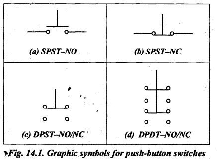
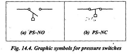
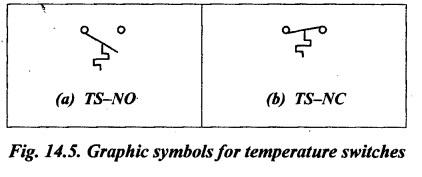
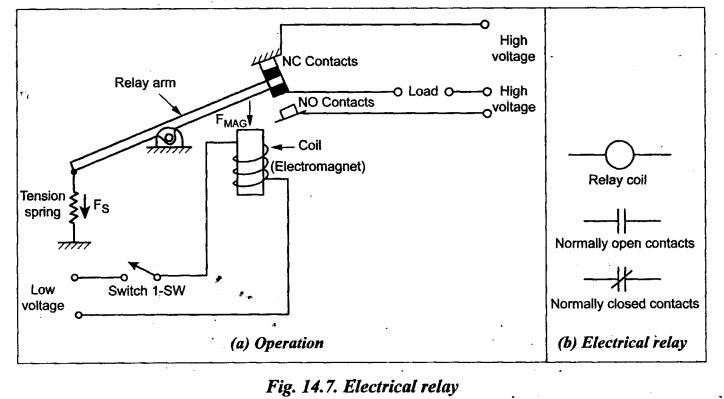
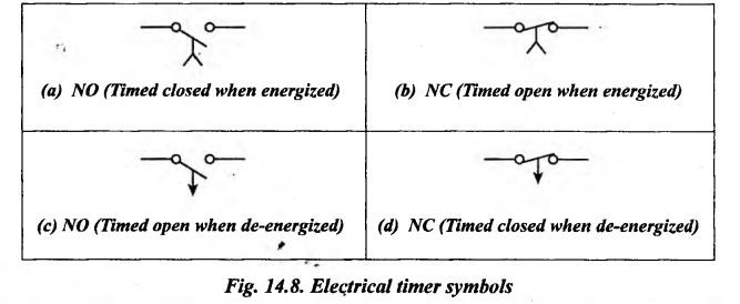
TYPES OF ELECTRICAL CONTROL DEVICES The most commonly used electrical control devices are : 1. Push-button switches, 2. Limit switches, 3. Pressure switches, 4. Temperature switches, 5. Solenoids, 6. Relays, and 7. Timers. • The push-button switches are primarily used for starting and stopping of the machinery. They also provide manual operation when an emergency arises. • The push-button switches are also called as 'momentary switches', because they make or break contact only as long as they are held under pressure. • Types: The four commonly used types of push-button switches are : (i) Single-pole single-throw - Normally open type (SPST-NO), (ii) Single-pole,single-throw - Normally close type (SPST-NC), (iii) Double-pole single-throw type (DPST), and (iv) Double-pole double-throw type (DPDT). • Fig.14.1 shows the symbolic representation for the above types of push-button switches. • As shown in Figs. 14.1(a) and (b), the single-pole single-throw type has one normally open and one normally closed pair of contacts. • As shown in Figs. 14.1(c) and (d), the double-pole double-throw arrangement has two pairs of normally open and two pairs of normally closed contacts to allow the inverting of two circuits with single input. • The limit switches are used to identify the extreme limits of the cylinder actuation. • Difference: The difference between the push-button and limit switches is that the push-button switches are actuated manually whereas the limit switches are mechanically actuated devices. • Types: Fig.14.2 shows the graphic symbols for the commonly used limit switches. • In Fig.14.2(a), LS-NO means a limit-switch normally-open. Fig.14.2(b) shows a normally open limit-switch that is held closed. In Fig.14.2(c), LS-NC means a limit- switch normally-closed. Fig.14.2(d) shows a normally closed type limit-switch that is held open. • Fig.14.3 shows a hydraulic cylinder that has built-in limit switches, one at each end of the cylinder. • There are many operators available such as cams, levers, rollers, and plungers to mechanically actuate the limit switches. • The pressure switches are used to sense a change in pressure automatically, and opens or closes an electrical switch when a predetermined pressure is reached. • They have usually two pressure settings, namely high and low pressure. For example, in a circuit it may be required to stop a pump to maintain a given pressure. In this circuit, the low-pressure setting will start the pump and the high-pressure setting will stop the pump. • Fig.14.4 shows the graphic symbols used for pressure switches. • Fig.14.4(a) shows a normally open pressure switch, which is abbreviated PS-NO. Fig.14.4(b) depicts a pressure switch which is normally closed. • The temperature switches are used to sense a change in temperature automatically, and opens or closes an electrical switch when a predetermined temperature is reached. • Like other switches, these switches are also wired either normally open or normally closed. • Fig.14.5 shows the graphic symbols used for temperature switches. • Fig.14.5(a) shows a normally open type temperature switch and Fig.14.5(b) shows the normally closed type. • A solenoid is an electromagnetic mechanical transducer that converts an electrical signal into a mechanical output force. • Solenoids provide a push or pull force to remotely operate fluid power valves. • Fig.14.6(a)'shows the graphical symbol used to represent the solenoid. • An indicator lamp is used to indicate the state of a specific circuit components. • Indicator lamps are used : (i) to identify which solenoid operator of a DC valve is energized, and (ii) to indicate whether a hydraulic cylinder is extending or retracting. • Fig.14.6(b) shows the symbolic representation of an indicator lamp. 1. What are Relays ? • The electrical relays offer simple ON/OFF switching action in response to a signal issued by a control system. • In other words, relays are nothing but electrically operated switches. • Relays are commonly used to open or close the contacts and thereby energize or de- energize solenoids which operate at a high current level. A low-voltage circuit can be '. used to energize relay coils that control high-voltage contacts used to open and close. circuits containing the solenoids. 2. Operating Principle Fig.14.7(a) illustrates the operating principle of an electrically operated relay switch. When switch 1-SW is closed, the current flows through the coil of wire and thus a magnetic field is produced. This pulls a spring-loaded moveable relay arm that forces the contacts to open or close. Usually there are two sets of contacts with upper one being normally closed (NC) contacts, and the lower one is normally open (NO) contacts. 3. Graphic Symbols Fig.14.7(b) shows the graphical symbols for the relay coil and the symbols for the normally open and closed contacts. • Timers, also known as time-delay relays, are time delay switches used to control the time duration of a working cycle. • Timers are commonly applied in electrical control circuits when a time delay from the instant of actuation to the closing of contacts is required. • These timers can be adjusted to change the dwell period for many machining® operations. For example, in a drilling machine operation the timers provide a dwell, which allows the drill to pause for a predetermined time at the end of the stroke to remove the chips. • The symbolic representation of the timers is shown in Fig.14.8. • Fig.14.8(a) shows a normally open switch when energized closes after a predetermined time interval. Fig.14.8(b) shows a normally closed timer switch that is time opened when energized. Fig.14.8(c) shows the normally open timer switch that is timed when de-energized. Fig.14.8(d) shows the normally closed timer switch that is time closed when de-energized.1. Push-button Switches
2. Limit Switches

3. Pressure Switches
4. Temperature Switches
5. Solenoids

6. Relays
7. Timers or Time-Delay Relays
Hydraulics and Pneumatics: Unit IV: Pneumatic and Electro Pneumatic Systems : Tag: : Pneumatic and Electro Pneumatic Systems - Hydraulics and Pneumatics - types of electrical control devices
Related Topics
Related Subjects

Hydraulics and Pneumatics
ME3492 4th semester Mechanical Dept | 2021 Regulation | 4th Semester Mechanical Dept 2021 Regulation