Hydraulics and Pneumatics: Unit IV: Pneumatic and Electro Pneumatic Systems
ladder diagrams
Pneumatic and Electro Pneumatic Systems - Hydraulics and Pneumatics
It should be noted that while drawing any electrohydraulic (or electropneumatic) circuits, separate circuits should be drawn for the fluid system and the electrical system.
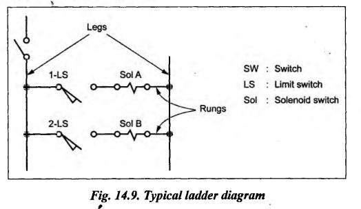
LADDER DIAGRAMS It should be noted that while drawing any electrohydraulic (or electropneumatic) circuits, separate circuits should be drawn for the fluid system and the electrical system. Also each components should be labeled so that one can understand exactly how the two systems interfaced. The second circuit showing the electrical system is known as ladder diagram. Thus the operation of the total system can be understood by examination of both the fluid power circuit and ladder diagram (i.e., electrical circuit). • A ladder diagram is a representation of hardware connections between switches, relays, solenoids, etc., which constitute the basic components of an electrical control system. • In other words, a ladder diagram is nothing but an electrical diagram showing the hardware connections between the various electrical control devices. Consider a typical ladder diagram as shown in Fig.14.9 for some application. • Legs and Rungs: In Fig.14.9, the two vertical electrical power supply lines are called 'legs', and the horizontal lines containing electrical components are called 'rungs'. • In ladder diagrams, always the power is connected to the left leg and the ground is connected to the right leg. • It should be noted that always the switches should be shown in their unactuated (i.e., open) mode in the ladder diagrams. • Since the electric circuit diagram resembles to a ladder, this diagram is called a 'ladder diagram'. • Uses: Ladder diagrams provide a circuit designer with a practical means to examine input process and output functions to quickly plan the circuit layout design for a particular hydraulic or pneumatic application. Now we shall illustrate some important electrohydraulic and electropneumatic circuits with the use of ladder diagrams.1. Introduction
2. What is Meant by a Ladder Diagram?
3. Details of a Ladder Diagram
Hydraulics and Pneumatics: Unit IV: Pneumatic and Electro Pneumatic Systems : Tag: : Pneumatic and Electro Pneumatic Systems - Hydraulics and Pneumatics - ladder diagrams
Hydraulics and Pneumatics: Unit IV: Pneumatic and Electro Pneumatic Systems
Under Subject

Hydraulics and Pneumatics
ME3492 4th semester Mechanical Dept | 2021 Regulation | 4th Semester Mechanical Dept 2021 Regulation
Related Subjects

Environmental Sciences and Sustainability
GE3451 ESS 4th Semester | 2021 Regulation | 4th Semester EEE Dept 2021 Regulation

Theory of Machines
ME3491 4th semester Mechanical Dept | 2021 Regulation | 4th Semester Mechanical Dept 2021 Regulation
Thermal Engineering
ME3451 4th semester Mechanical Dept | 2021 Regulation | 4th Semester Mechanical Dept 2021 Regulation
Hydraulics and Pneumatics
ME3492 4th semester Mechanical Dept | 2021 Regulation | 4th Semester Mechanical Dept 2021 Regulation

Manufacturing Technology
ME3493 4th semester Mechanical Dept | 2021 Regulation | 4th Semester Mechanical Dept 2021 Regulation
Strength of Materials
CE3491 4th semester Mechanical Dept | 2021 Regulation | 4th Semester Mechanical Dept 2021 Regulation