Basic Electrical and Electronics Engineering: Unit I: Electrical Circuits
Three Phase Circuits
Star Connection, Mesh (or) Delta Connection, Advantages, problems with solution
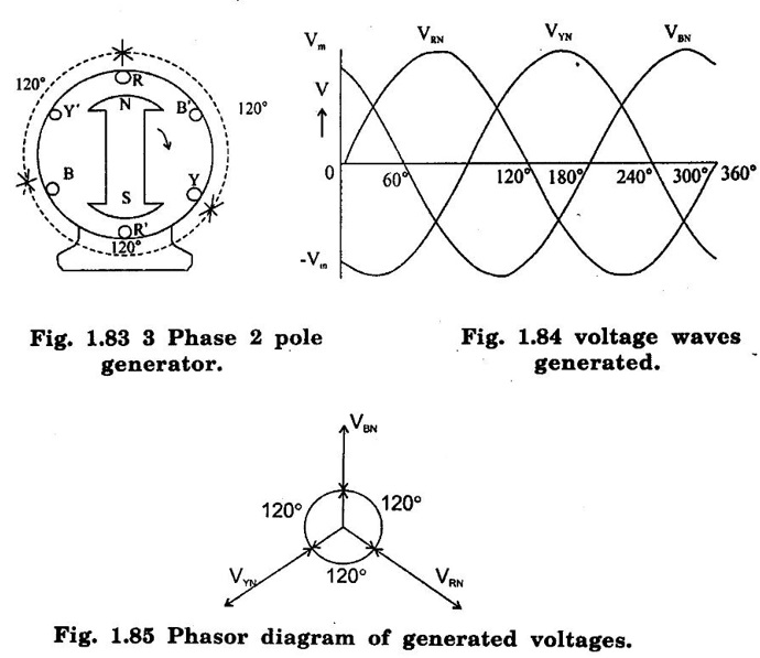
A 3-phase system will employ voltage sources which consists of 3 voltages substantially equal in magnitude and displaced by phase angle of 120°.
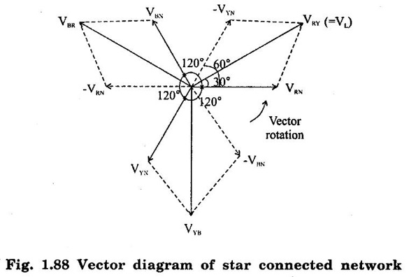
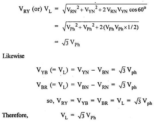
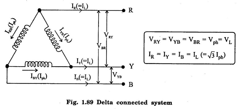
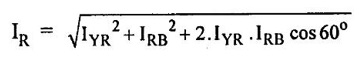
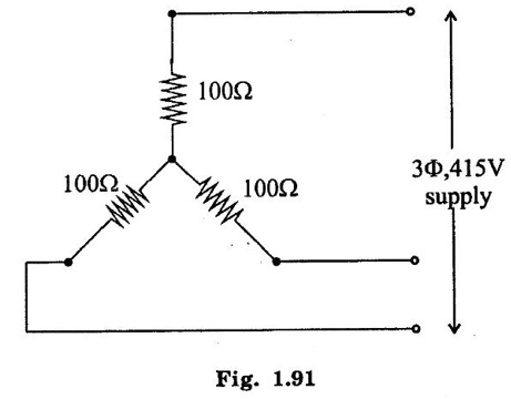
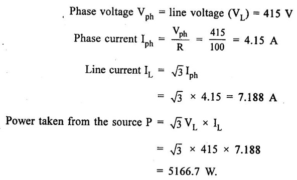
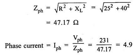
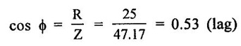
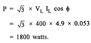
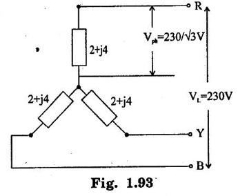
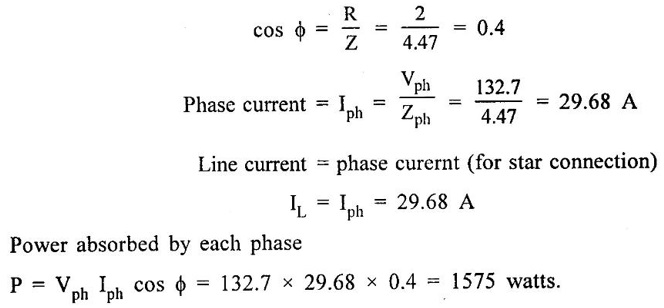
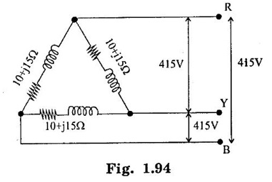
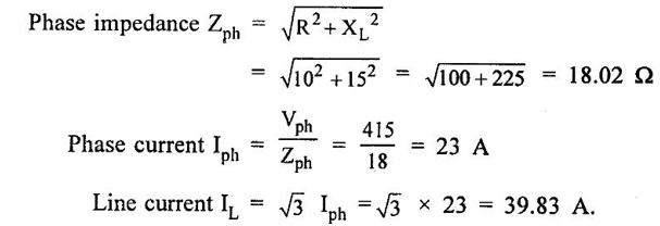
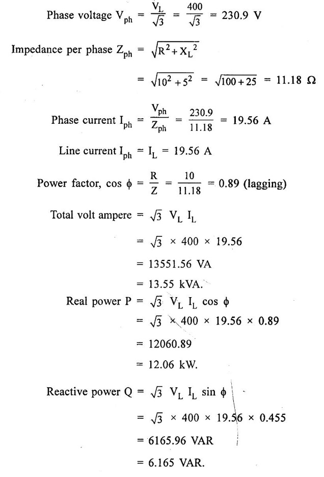
THREE PHASE CIRCUITS A 3-phase system will employ voltage sources which consists of 3 voltages substantially equal in magnitude and displaced by phase angle of 120°. 1. Polyphase transmission line require less conductor material than single phase line for transmitting same amount of power at the same voltage. 2. Polyphase motors have uniform torque. Single phase motors have pulsating torque. 3. Power rating is high for polyphase motor. 4. Polyphase induction motors are self starting and more efficient. 5. For same rating, power factor of polyphase motor is higher than single phase motors. In three phase system as shown in figure 1.83 (3 phase, 2 pole generator), three phase voltages can be generated by placing three rectangular coils displaced in space by 120° in a uniform magnetic field. When the field is excited and rotated, voltages will be generated in the three phases in accordance with faraday's law. These voltages are differ by 120°. The figure 1.84 shows these three waves will be displaced by 120 electrical degrees. Three winding are identical, hence the magnitudes of three voltages are equal. The instantaneous values of generated emf's in coils RR', YY' and BB' are given by The rms values (VRN, VYN VBN) of these three emfs have been represented by phasors in figure 1.85. The phase sequence is meant the order in which the phase voltages of a 3-phase system attain their peak or maximum positive values. The phase sequence RYB normally means that red phase is followed by yellow phase, which is followed by blue phase. When the voltage of red phase is at its maximum positive value, the voltage of Y phase will be 120° behind its maximum positive value and that of B phase will be 240° behind its maximum positive value as shown in figure 1.84. The phase sequence of these three voltages and phasors are assumed to rotate in counterclockwise direction. By interchanging the connections of any two phases, the phase sequences of particular system can be changed. Each coil of three phases has two terminals (start (S) and end (E)) and if individual phase is connected to separate load as shown in figure 1.86, there is a non- interlinked 3-phase system occur. Such an arrangement requires two conductors for each phase, that is total of six conductors for a 3-phase system. It causes the whole system complicated and expensive. Therefore the three phases are interconnected which results in great saving of copper used for conductors. The general method of interconnections are : 1. The star or wye (Y) connection 2. Delta (or) Mesh (Δ) connection Figure 1.87 shows that three windings are connected in star. In this method of inter-connection, the similar ends are joined together at point N (Neutral point). Only three wires are carried to the external circuit giving 3-phase, 3-wire system. If neutral wire also taken out then the system will be 3-phase, 4 wire system. The voltage between any line and neutral point is known as phase voltage (Vph). The voltage between any pair of terminals is known as line voltage (V1). The current flowing in any phase winding is called phase current and the current flowing in any line is called line current. In star connection, there are two phase windings between each pair of terminals, but since their similar ends have been joined together, they are in opposition. Therefore, the instantaneous value of potential difference between any two terminals is arithmetic difference of two phase emfs concerned. The potential difference is given by the vector difference of the two phase emfs. VRN = VYN = VBN = Vph (phase emf) Line voltage VRY = (VL) = Vectors difference of VR and VY. Line voltage VYB = VYN - VBN Line voltage VBR = VBN - VRN Voltage Relationship The potential difference between R and Y is VRY = VRN - VYN (Voltage difference) (or) = VRN + (-VYN) (Vector sum) VRY is found by compounding VRN and VYN reversed and its value is given by diagonal of parallelogram as shown in figure 1.88. The angle between VRN and VYN reversal is 60° and then value of (i.e.,) Line voltage is √3 times the phase voltage. In the star connected system, each line conductor is connected to separate phase, so the current flowing through the line and phase are same. (i.e.,) IR = IY = IB = Iph (i.e.,) IL = Iph In a three phase system, power per phase = Vph Iph cos ϕ where cos ϕ is power factor of the load. ϕ is phase angle between phase voltage and corresponding phase current. Hence total power fed to three phase system with balanced load P = 3 × power per phase = 3 × Vph Iph cos ϕ ...(1) We know that In balanced system, the potential of the neutral or star point is zero, (i.e.,) potential at neutral point. = VNR + VNY + VNB = 0 In delta connection, starting end of one phase is connected to the finishing end of another phase as shown in figure 1.89. In Delta connected system, only one phase is included between any pair of line outers, therefore potential difference between line outers called as line voltage which is equal to phase voltage. Line voltage VL = Phase voltage Vph. From the figure 1.90, line current is vector difference of phase current of two phases concerned. The line current IR = IYR – IRB = IYR + (−IRB) Similarly lY = IBY - IYB IB = IRB - IBY From the figure 1.90, the phase angle between phase current IYR and - IRB is 60° Assuming the delta connected system is balanced, phase current in each winding is equal and let each be equal to Iph. (i.e., IYR = IBY = IRB = Iph) Power per phase = Vph Iph cos ϕ Total power of 3 phase system, P = 3 Vph Iph cos ϕ Hence, above expression for power becomes In balanced system, the resultant emf in the closed circuit will be zero. (i.e.,) VRY + VYB + VBR = 0 Therefore, there is no circulating current in the mesh if no load is connected to the lines. Balanced supply A supply is said to be balanced if all three voltages are equal in magnitude and displaced by 120°. Balanced Load A load is said to be balanced if the impedances in all three phases are equal in magnitude and phase. Problem 1.35 Three 100 Ω resistors are connected in star and then delta across 415 V, 3 phase supply. Calculate the line and phase currents in each case and also the power taken from the source. Solution: (i) Star connection In star connection, the line current = phase current. To find phase current, phase voltage must be known. Hence (ii) Delta connection In delta connection, the line voltage = phase voltage To find line current, phase current and phase voltage must be known, Problem 1.36 Three equal impedances each having resistance of 25Ω and inductive reactance of 40Ω are conneted in star to a 400 V, 3-phase, 50 Hz system. Calculate (a) line current (b) Power factor (c) Power consumed. Solution : (a) Line current (I1) Line voltage VL = 400 V Impedance per phase, Line current is equal to phase current for star connected system. Therefore Line current IL = 4.9 A. (b) Power factor (cos ϕ) (c) Power consumed (P) Problem 1.37 In a 3 phase, 3 wire system with star connected load the impedance of each phase is (2 + j4Ω). If the line voltage is 230 V. Calculate (i) the line current, (ii) the power absorbed by each phase. Solution : Line voltage VL = 230 V Power factor (cos ϕ) Problem 1.38 A 415 V phase voltage is applied to balance delta connected load of phase impedances each equal to 10+ j15 Ω Find (i) Phase and current (ii) Power consumed per phase. Solution : (i) Phase current and line current To find Iph and IL, we need Vph and Zph. So, Vph = VL = 415 V (for delta connection) (ii) Power consumed per phase Problem 1.39 A three phase balanced load of (10 + j5) Ω per phase is connected to a 3-phase, 400 V, 50 Hz supply. Find the line current, power factor, total volt ampere, real power and reactive power. Solution : (i) Line current (I1) : 1.107 To find line current, we need to know phase voltage and phase impedance.Advantages of Polyphase systems.

Phase sequence
Inter-connection of three phases

1. Star Connection

Current Relationship
Power

2. Mesh (or) Delta Connection
Voltage relationship
Current Relationship
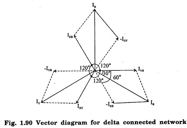

Power


Basic Electrical and Electronics Engineering: Unit I: Electrical Circuits : Tag: : Star Connection, Mesh (or) Delta Connection, Advantages, problems with solution - Three Phase Circuits
Related Topics
Related Subjects

Basic Electrical and Electronics Engineering
BE3251 2nd semester Mechanical Dept | 2021 Regulation | 2nd Semester Mechanical Dept 2021 Regulation

Basic Electrical and Electronics Engineering
BE3251 2nd Semester CSE Dept 2021 | Regulation | 2nd Semester CSE Dept 2021 Regulation