Theory of Machines: Unit I: Kinematics of Mechanisms
synthesis of cam profile
Kinematics of Mechanisms - Theory of Machines
If follower motion has been selected/specified, the displacement diagram for the same can be drawn to a suitable scale.
SYNTHESIS OF CAM PROFILE
(Construction of Cam Profile for a Radial Cam)
• If follower motion has been
selected/specified, the displacement diagram for the same can be drawn to a
suitable scale. Using this displacement diagram, the cam profile can be drawn
with the same scale.
• The method of drawing cam profile
depends on the type of follower and position of the axis (i.e., in-line or
offset).
• The construction of cam profile is in
fact based on the principle of inversion.
• In order to obtain the inversion, the
oam is held stationary and the follower is imagined to move around the cam in
the opposite direction that of the cam rotation.
• The following examples illustrate the
construction of cam profiles for different types of follower with different
types of follower motion.
Note
1.
It should be remembered that the radius of base circle is called the least
radius of the cam.
2.
If the radius of base circle is not given in the problem, a suitable radius can
be assumed. Bigger the base circle radius, bigger the cam size; but the cam
profile do not change.
3.
If offset (ie., eccentricity) of follower is not given, then the follower axis
may be assumed to pass through the centre of the cam.
4.
If the direction of rotation of cam is not given, then the direction of
rotation may be assumed (say, clockwise direction).
1. Cam Profile with Knife-Edge Follower
Example 3.1
A cam operating a knife-edged follower has the following data:
(a) Follower moves outwards through 40 mm during 60° of cam
rotation.
(b) Follower dwells for the next 45°.
(c) Follower returns to its original position during next 90°.
(d) Follower dwells for the rest of the rotation.
The displacement of the follower is to take place with uniform
velocity during the both outward and return strokes. The least radius of the
cam is 50 mm. Draw the profile of the cam when:
(1) the axis of the
follower passes through the cam axis, and
(2) the axis of the follower is offset by 18 mm towards right
from the cam axis.
Given data:
Knife-edged
follower; Follower lift, L = 40 mm; Angle for rise, θ0 = 60°; Angle
for return, θr = 90°; Least radius of cam, rb
= 50 mm.
Solution: Construction:
Since the follower is moving with uniform velocity during both outward and
return strokes, therefore draw the displacement diagram of the follower, by
assuming suitable scale, as explained in Section 3.6.1. The displacement
diagram so obtained is shown in Fig.3.22.

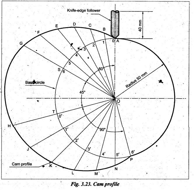
(1) Profile of the cam
when the axis of follower passes through the axis of cam-shaft:
The
cam profile when the axis of the follower passes through the axis of the
cam-shaft is drawn, as shown in the Fig.3.23, using the procedure given below.
Procedure:
(a)
Draw a base circle with minimum radius of the cam (= 50 mm) with O as centre
(using same scale that was used for displacement diagram).
(b)
Since the direction of rotation of the cam is not given, assume it as clockwise
direction. Therefore for drawing cam profile, cam is assumed stationary and
follower is taken around the cam in anticlockwise direction.
(c)
Since the axis of the follower passes through the axis of the camshaft,
therefore mark trace point A, as shown in Fig.3.23. Now, from OA, mark ![]() AOS
= θ。 = 60°,
AOS
= θ。 = 60°, ![]() SOT=
θd = 45°, and
SOT=
θd = 45°, and ![]() TOP = θr = 90° on
base circle in anticlockwise direction.
TOP = θr = 90° on
base circle in anticlockwise direction.
(d)
Divide cam angles θ。
and θr into the same number of equal even parts (say 6) as in
displacement diagram. Join the points 0, 1, 2, ......, 6 and 0', 1', ..., 6'
with centre O and produce beyond the base circle as shown in Fig.3.23..
(e)
Now transfer distances 0A, 1B, 2C, ......, 6G, and O'H, 1'J, 2'K, …., 6'P, from
the displacement diagram on the extended radial lines above the base circle, to
obtain points A, B, C, ......, G and H, J, K, ..., P.
(f)
Join the points A, B, C, ..., with a smooth curve and the resulting curve AGHPA
is the required cam profile.
(2) Profile of the cam
when the axis of the follower is offset by 18 mm towards the right from the cam
axis:
The
cam profile when the axis of the follower is offset from the axis of the
camshaft is drawn, as shown in the Fig.3.24, using the procedure given below.
Procedure:
(a)
Draw a base circle with minimum radius of the cam (= 50 mm) with O as centre (using
same scale that was used for displacement diagram).
(b)
Since the direction of rotation of the cam is not given, assume it as clockwise
direction. Therefore for drawing cam profile, cam is assumed stationary and
follower is taken around the cam in anticlockwise direction.
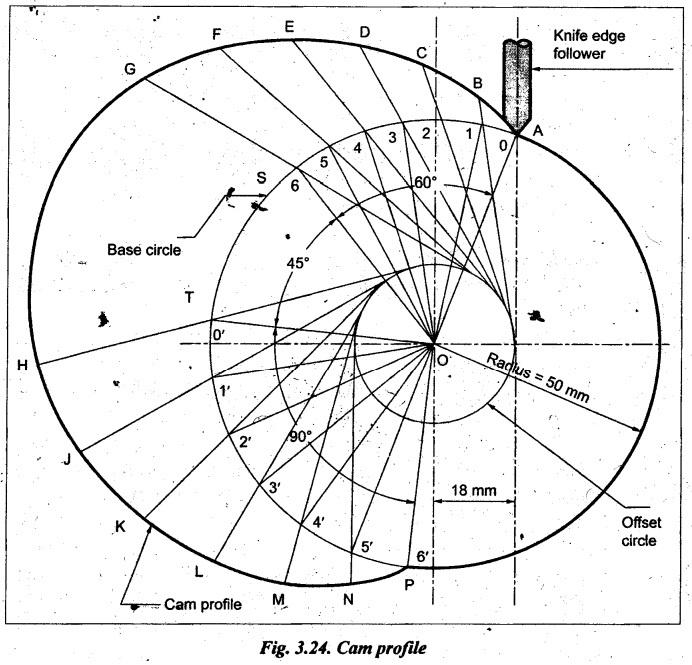
(c)
Since the axis of the follower is offset from the axis of the camshaft,
therefore draw the axis of the follower at a distance of 18 mm towards right
from the axis of cam which intersects base circle at 'A' (trace point).
(d)
Join AO and draw an offset circle of radius 18 mm with centre O.
(e)
Now, from OA, mark ![]() AOS = θ0 = 60°,
AOS = θ0 = 60°, ![]() SOT = θd
= 45°, and
SOT = θd
= 45°, and ![]() TOP = θr = 90° on base circle in
anticlockwise direction.
TOP = θr = 90° on base circle in
anticlockwise direction.
(f)
Divide cam angles θ0 and θr into the same
number of equal even parts (say 6) as in displacement diagram. Now from the
points 0, 1, 2, ............., 6, and 0', 1', 2', ..., 6′, on the base circle,
draw tangents to the offset circle and produce these tangents beyond the base
circle as shown in Fig.3.24.
(g)
Now transfer distances 0A, 1B, 2C, 6'P, and O'H, 1′J, 2′K, …, 6’P, from the
displacement diagram on the extended tangent lines above the base circle, to
obtain the points A, B, C,..., G and H, J, K, ..., .
(h)
Join the points A, B, C, ..., with a smooth curve and the resulting curve AGHPA
is the required cam profile.
Example 3.2
A cam is to be designed for a knife-edge follower with the
following data:
■ Follower lift is 40 mm with SHM, during 90° of cam rotation.
■ Dwell for the next 30°.
■ Follower return to its original position with SHM, during the
next 60° of cam rotation.
■ Dwell for the remaining cam rotation.
The line of stroke of the follower passes through the axis of
the camshaft. Radius of the base circle of the cam is 40 mm.
(i) Draw the displacement diagram.
(ii) Draw the profile of the cam.
(iii) Determine the maximum velocity and acceleration of the
follower during forward and return strokes, if the cam rotates at 200 rpm in
clockwise direction.
Given data:
Knife-edge
follower; Follower lift, L = 40 mm; Angle for rise, θ0 = 90°; Angle
for dwell, θd = 30°; Angle for return, θr =
60°; Radius of base circle of cam, rb =40 mm; N=200 rpm (CW).
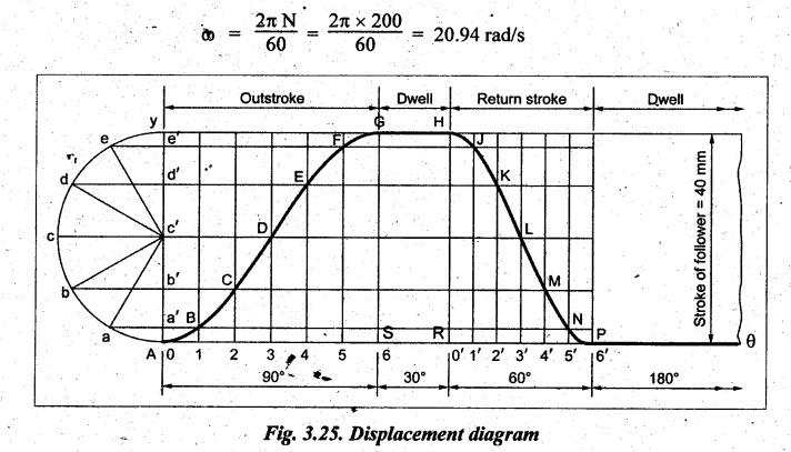
Solution: (i) Construction
of displacement diagram: Since the follower is moving with SHM during
both outward and return strokes, therefore draw the displacement diagram of the
follower, by assuming suitable scale, as explained in Section 3.7.1. The
displacement diagram so obtained is shown in Fig.3.25.
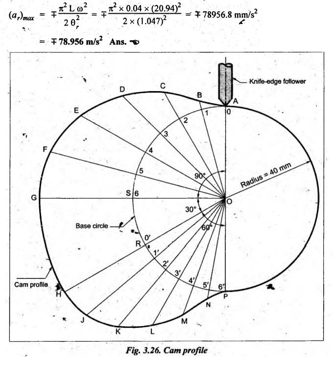
(ii) Profile of the
cam when the axis of follower passes through the axis of camshaft:
The
cam profile when the axis of the follower passes through the axis of the
camshaft is drawn, as shown in the Fig.3.26, using the same procedure discussed
in Example 3.1.
(iii) Maximum velocity
and acceleration of the follower during forward and return strokes:
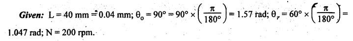
We
know that the angular velocity of the cam,
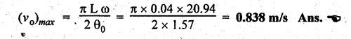
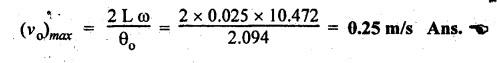
Maximum velocity of
follower during forward and return strokes:
We
know that maximum velocity of follower having SHM during forward stroke,
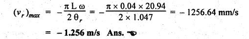
and
maximum velocity of follower having SHM during return stroke,
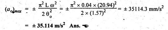
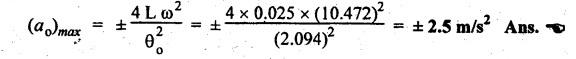
Maximum
acceleration of follower during forward and return strokes:
We
know that maximum acceleration of follower having SHM during forward stroke,
and
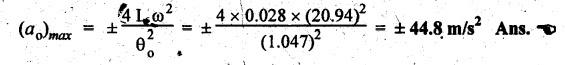
maximum acceleration of follower having SHM during return stroke,
Example 3.3
A cam is to be designed for a knife-edge follower with the
following data:
(i) Cam lift = 40 mm during 90° of cam rotation with simple
harmònic motion.
(ii) Dwell for the next 30°.
(iii) During the next 60o of cam rotation, the follower returns
to its original position with simple harmonic motion.
(iv) Dwell for the remaining 180°
Draw the profile of the cam when the line of stroke is offset 20
mm from the axis of the camshaft. The radius of the base circle of the cam is
40 mm.
Given data:
Knife-edge follower; Follower lift, L = 40 mm; Angle for rise, θ0 =
90°; Angle for dwell, θd = 30°; Angle for return, θr
= 60°; Radius of base circle of cam, rb = 40 mm.
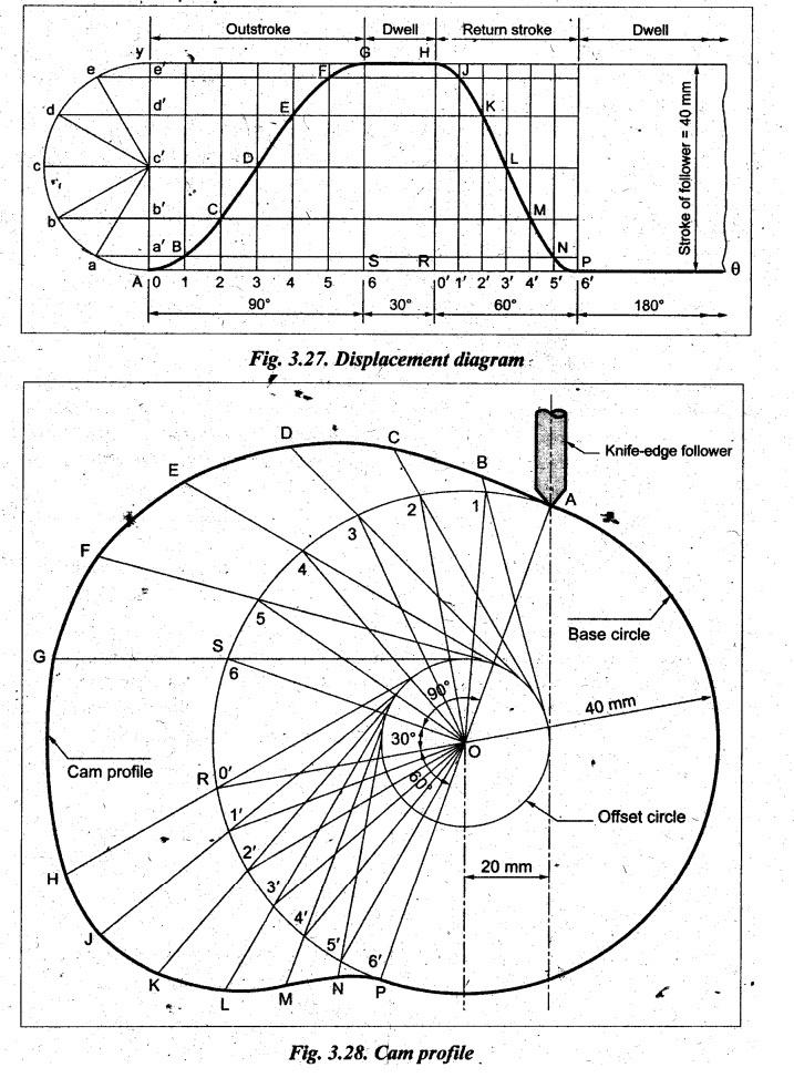
Solution: (i) Construction
of displacement diagram: Since the follower is moving with SHM during
both outward and return strokes, therefore draw the displacement diagram of the
follower, by assuming suitable scale, as explained in Section 3.7.1. The
displacement so obtained is shown in Fig.3.27.
(ii) Profile of the
cam when the axis of follower passes through the axis of camshaft:
The
cam profile when the axis of the follower passes through the axis of the
camshaft is drawn, as shown in the Fig.3.28, using the same procedure discussed
in Example 3.1.
Example 3.4
A cam rotating clockwise at a uniform speed of 100 rpm is
required to give motion to knife-edge follower as below:
(a) Follower to move outwards through 25 mm during 120° of cam
rotation.
(b) Follower to dwell for the next 60° of cam rotation.
(c) Follower to return to its starting position during next 90°
of cam rotation.
(d) Follower to dwell for the remaining 90° of cam rotation.
The minimum radius of cam is 50 mm. Draw the profile of the cam
when the line of stroke of the follower passes through the axis of the
camshaft. If the displacement of the follower takes place with uniform and
equal acceleration and retardation on both the outward and return strokes, find
the maximum velocity and acceleration during its outstroke and return stroke.
Also draw the displacement, velocity and acceleration diagrams
for one complete revolution of the cam.
Given data:
Knife-edge
follower; Follower lift, L = 25 mm; Angle for rise, θ0 = 120°; Angle
for dwell, θd = 60°; ; Angle for return, θr
= 90°; Radius of base circle of cam, rb = 50 mm; N=100 rpm.
Solution: Construction of
displacement diagram: Since the follower is moving with uniform
acceleration and retardation motion (UARM) during both outward and
return strokes, therefore draw the displacement diagram of the follower, by
assuming suitable scale, as explained in Section 3.8.1. The displacement
diagram so obtained is shown in Fig.3.29.
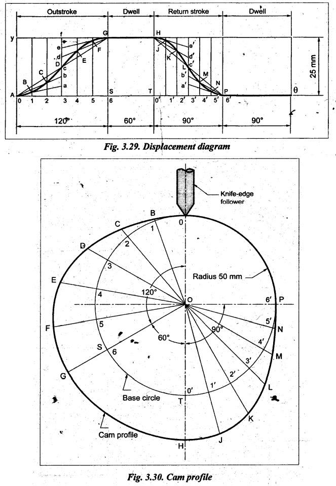
Profile of the cam
when the axis of follower passes through the axis of camshaft:
The
cam profile when the axis of the follower passes through the axis of the
camshaft is drawn, as shown in Fig.3.30, using the same procedure discussed in
Example 3.1.
Maximum velocity and
acceleration of the follower during forward and return strokes:
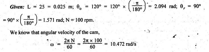
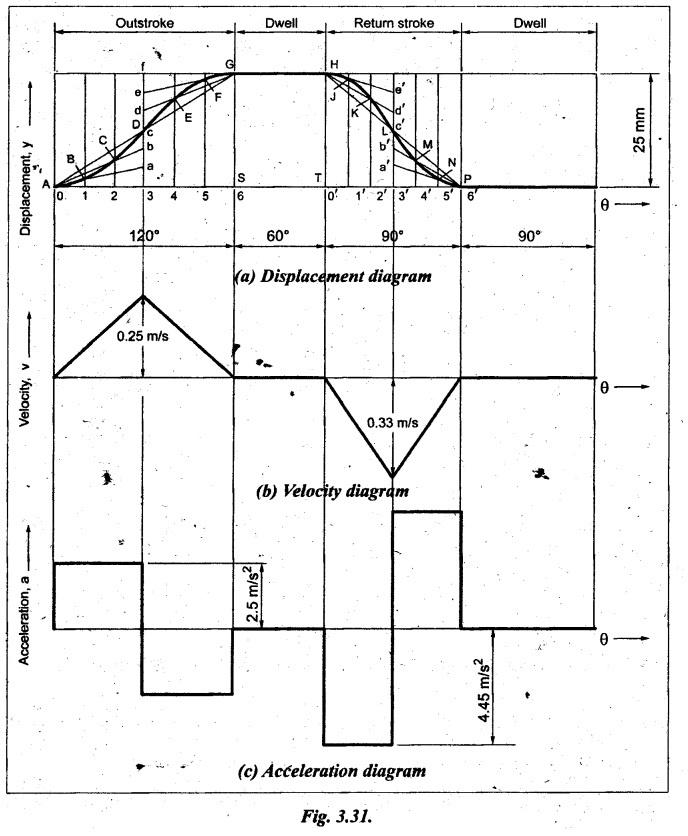
Maximum velocity of
follower during forward and return strokes:
We
know that maximum velocity of follower having UARM during forward stroke,

and
maximum velocity of follower having UARM during return stroke,
Maximum acceleration
of follower during forward and return strokes:
We
know that maximum acceleration of follower having UARM during forward stroke,
and
maximum acceleration of follower having UARM during return stroke,

The
displacement, velocity and acceleration diagrams are drawn, as shown in
Fig.3.31.
Example 3.5
Draw the profile of a cam operating with a knife-edged follower
having a lift of 30 mm. The cam raises with SHM for 150° of its rotation
followed by a period of dwell for 60°. The follower descends for the next 100°
rotation of the cam uniform velocity, again followed by a dwell period. The cam
rotates at a uniform velocity of 120 rpm and has a least radius of 20 mm.
[A.U.,
Nov/Dec 2010]
Given data:
Knife-edge
follower; Follower lift, L = 30 mm; Angle for rise, θ0 = 150°; Angle
for dwell, θd = 60°; Angle for return, θr =
100°; N 120 rpm; Minimum radius of cam, rb = 20 mm.
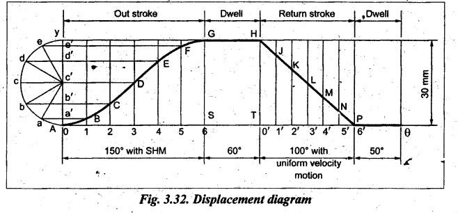
Solution: Construction of
displacement diagram: For forward stroke, since the follower is moving
with SHM, the displacement diagram is drawn as shown in Fig.3.32, by assuming suitable
scale, as explained in Section 3.7.1. Similarly, for return stroke, since the
follower is moving with uniform velocity, the displacement
diagram is drawn in Fig.3.32, as explained in Section 3.6.1. The complete
displacement diagram so obtained is shown in Fig.3.32.
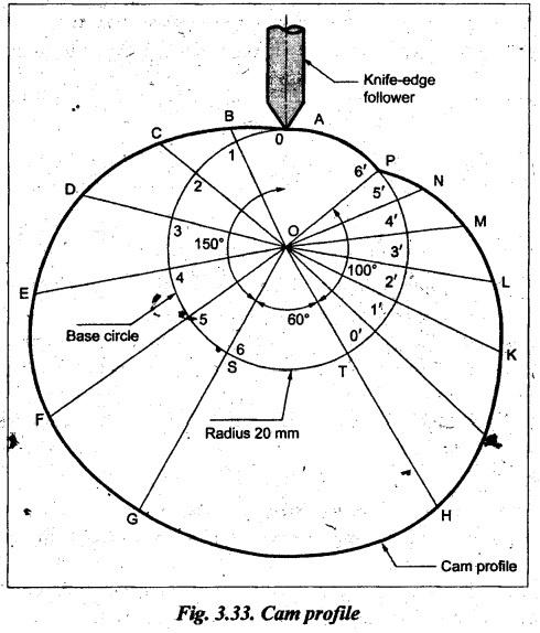
Profile of the cam
when the axis of follower passes through the axis of camshaft:
The
cam profile when the axis of the follower passes through the axis of the
camshaft is drawn, as shown in the Fig.3.33, using the same procedure discussed
in Example 3.1.
Example 3.6
A disc cam used for moving a knife-edge follower with simple
harmonic motion during lift and uniform acceleration and retardation motion
during return rotates in clockwise direction at 300 rpm. The line of motion of
the follower has an offset 10 mm to the right of camshaft axis. The minimum
radius of the cam is 30 mm. The lift of the follower is 40 mm. The cam rotation
angles are: Lift 60°, dwell 90o, return 120° and remaining angle for dwell.
Draw the cam profile and determine the maximum velocity and acceleration during
the lift and return.
Given data:
Knife-edge
follower; N = 300 rpm (CW); Offset = 10 mm; Minimum radius of cam, rb=
30 mm; Follower lift, L= 40 mm; Angle for rise, θ0 = 60°; Angle for dwell, dwell, θd
= 90°; Angle for return, θr = 120°.
Solution:
Construction
of displacement diagram: For forward stroke,
since the follower is moving with SHM, the displacement diagram is drawn as
shown in Fig.3.34, by assuming suitable scale, as explained in Section 3.7.1.
Similarly, for return stroke, since the follower is moving with uniform
acceleration and retardation motion (UARM), the displacement diagram is
drawn in Fig.3.34, as explained in Section 3.8.1. The complete displacement
diagram so obtained is shown in Fig.3.34.
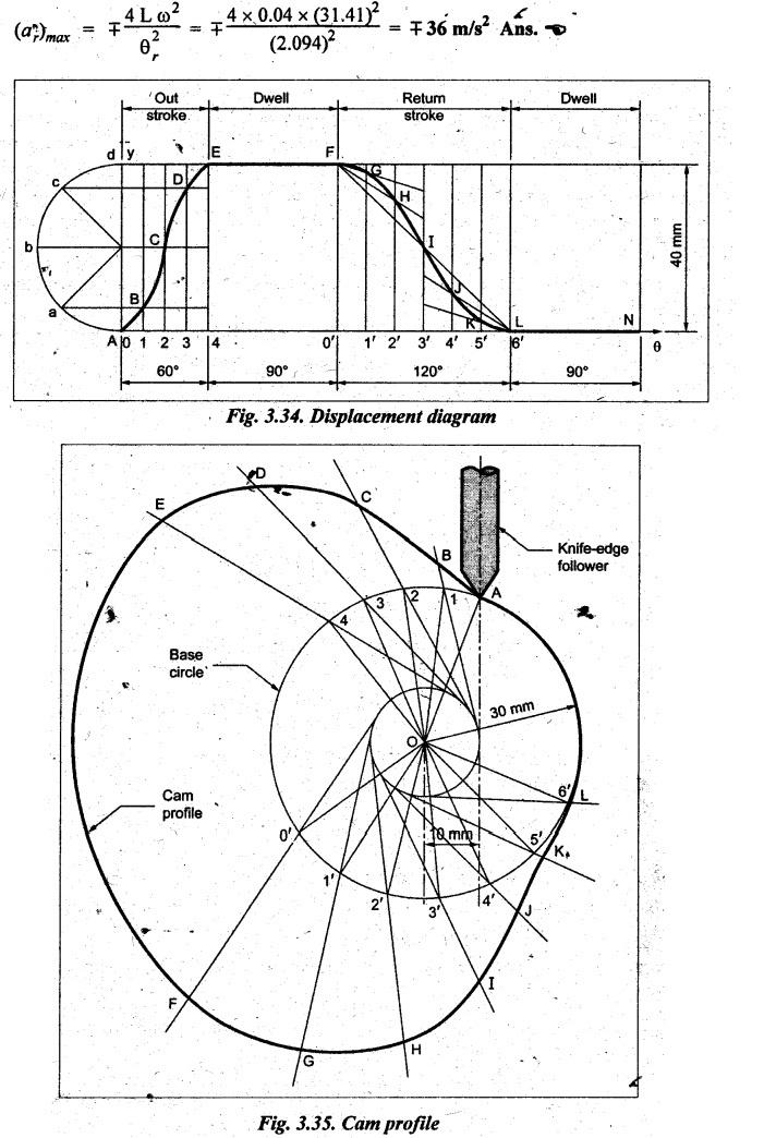
Profile of the cam
when the axis of the follower is offset by 18 mm towards the right from the cam
axis:
The
cam profile when the axis of the follower is offset from the axis of the
camshaft is drawn, as shown in the Fig.3.35, using the same procedure discussed
in Example 3.1.
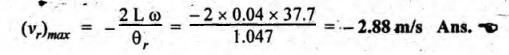
Maximum velocity and
acceleration during the lift and return:
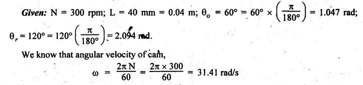
Maximum velocity of
follower during the lift and return:
Since
the follower moves with SHM during lift, therefore the maximum velocity of the
follower during forward stroke is given by

Similarly,
since the follower moves with UARM during return, therefore the maximum
velocity of the follower during return stroke is given by
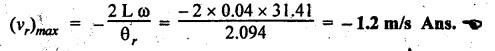
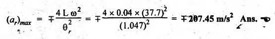
Maximum acceleration
of follower during the lift and return:
Since
the follower moves with SHM during lift, therefore the maximum acceleration of
the follower during forward stroke is given by
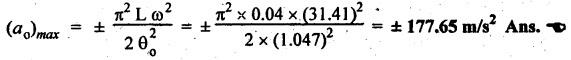
Similarly,
since the follower moves with UARM during return, therefore the maximum acceleration
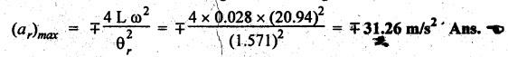
of the follower during return stroke is given by
2. Cam Profile with Roller Follower
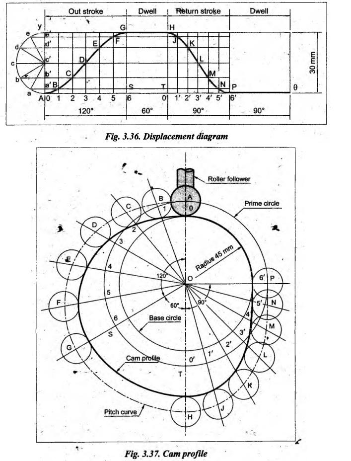
Example 3.7
A cam rotating clockwise with a uniform speed is to give the
roller follower of 20 mm diameter with the following motion.
(a) Follower to move outwards through a distance of 30 mm during
120° of cam rotation;
(b) Follower to dwell for 60° of cam rotation;
(c) Follower to return to its initial position during 90° of cam
rotation; and
(d) Follower to dwell for the remaining 90° of cam rotation.
The minimum radius of the cam is 45 mm and the displacement of
the follower is to take place with simple harmonic motion on both the outward
and return strokes. Draw the cam profile when:
(i) the line of stroke of the follower passes through the axis
of the camshaft, and
(ii) the line of stroke of the follower is offset by 15 mm from
the axis of the cam.
[A.U., Apr/May 2011]
Given data:
Roller follower; Diameter of roller, dr = 20 mm; Follower
lift, L = 30 mm; Angle for rise, θ。=
120°; Angle for dwell, θd = 60°; Angle for return, θr
= 90°; Minimum radius of cam, rb = 45 mm.
Solution: Construction of
displacement diagram: Since the follower is moving with SHM
during both outward and return strokes, therefore draw the displacement diagram
of the follower, by assuming suitable scale, as explained in Section 3.7.1. The
displacement diagram so obtained is shown in Fig.3.36.
(i) Profile of the cam
when the axis of follower passes through the axis of camshaft:
The
cam profile when the axis of the follower passes through the axis of the
camshaft is drawn, as shown in the Fig.3.37, using the procedure given below.
Procedure:
(a)
Draw a base circle with minimum radius of the cam (rb = 45
mm) with O as centre (using same scale that was used for displacement diagram).
(b)
Draw another circle, called pitch circle, with same centre with radius equal to
minimum radius of the cam plus roller radius (i.e., rb +
rr = 45 + (20/2) = 55 mm).
(c)
Since the cam rotates in clockwise direction, therefore for drawing cam
profile, cam is assumed stationary and follower is taken around the cam in
anticlockwise direction.
(d)
Since the axis of the follower passes through the axis of the camshaft,
therefore mark trace point A, as shown in Fig.3.37. Now, from OA, mark ![]() AOS =
θo = 120°,
AOS =
θo = 120°, ![]() SOT = θd = 60°, and
SOT = θd = 60°, and ![]() TOP = θr
= 90° on prime circle in anticlockwise direction.
TOP = θr
= 90° on prime circle in anticlockwise direction.
(e)
Divide cam angles θo and θr into the same number
of equal even parts (say 6) as, in displacement diagram. Join the points 0, 1,
2, ..., 6 and 0', 1', ......, 6' with centre O and produce beyond the prime
circle as shown in Fig.3.37.
(f)
Now transfer distances 0A, 1B, 2C, ……, 6G, and O'H, 1'J, 2'K, ......, 6'P, from
the displacement diagram on the extended radial lines above the prime circle,
to obtain points A, B, C, G and H, J, K, ................, P.
(g)
Joint the points A, B, C, .... ......., N, P, A. The curve drawn through these
points is known as pitch curve.
(h)
Now, from the points A, B, C, ......, P, draw circles of radius equal to the
radius of roller. Draw a smooth curve by free hand tangential to all the
circles, which is the required cam profile.
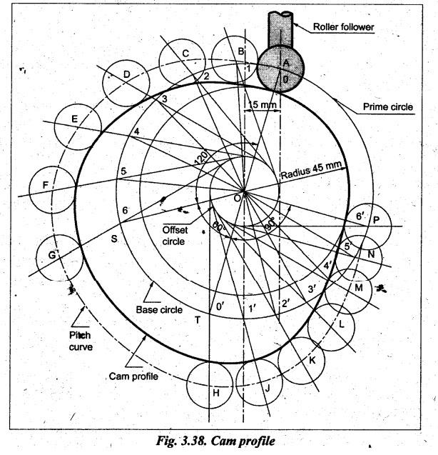
(ii) Profile of the
cam when the axis of the follower is offset by 15 mm towards the right from the
cam axis:
The
cam profile when the axis of the follower is offset from the axis of the
camshaft is drawn, as shown in Fig.3.38, using the procedure given below.
Procedure:
(a)
Draw a base circle with minimum radius of the cam (rb = 45
mm) with O as centre (using same scale that was used for displacement diagram).
(b)
Draw another circle, called pitch circle, with same centre O with radius equal
to minimum radius of the cam plus roller radius (i.e., rb = rr
= 45 + (20/2) = 55 mm).
(c)
Draw a third circle, called offset circle, with same centre O with radius equal
to offset distance (= 15 mm).
(d)
Since the cam rotates in clockwise direction, therefore for drawing cam
profile, cam is assumed stationary and follower is taken around the cam in
anticlockwise direction.
(e)
Since the axis of the follower is offset from the axis of the camshaft,
therefore draw the axis of the follower at a distance of 15 mm towards right
from the axis of cam which intersects base circle at 'A' (trace point). Join
AO.
(f)
Now, from OA, mark  on prime circle in anticlockwise direction.
(g)
Divide cam angles 0 and 0, into the same number of equal even parts (say 6) as
in displacement diagram. Now from the points 0, 1, 2, 6, and 0', 1', 2', ….,6',
on the prime circle, draw tangents to the prime circle and produce these
tangents beyond the prime circle as shown in Fig.3.38.
(h)
Now transfer distances 0A, 1B, 2C,......, 6G, and O'H, 1'J, 2K, ......, 6'P,
from the displacement diagram on the extended tangent lines above the prime
circle, to obtain the points A, B, C, .........., G and H, J, K, .., P.
(i)
Join the points A, B, C, ...., N, P, A. The curve drawn through these points is
known as pitch curve.
(j)
Now, from the points A, B, C, ......, P, draw circles of radius equal to the
radius of roller. Draw a smooth curve by free hand tangential to all the
circles, which is the required cam profile.
Example 3.8
Design a cam to raise a valve with. SHM through 50 mm in 1/3 of
a revolution, keep it fully raised through 1/12 revolution and to lower it with
harmonic motion in 1/6 revolution. The value remains closed during the reset of
the revolution. The diameter of roller is 20 mm and minimum radius of the cam
is 25 mm. The diameter of camshaft is 25 mm. The axis of the valve rod passes
through the axis of the camshaft.
Given data:
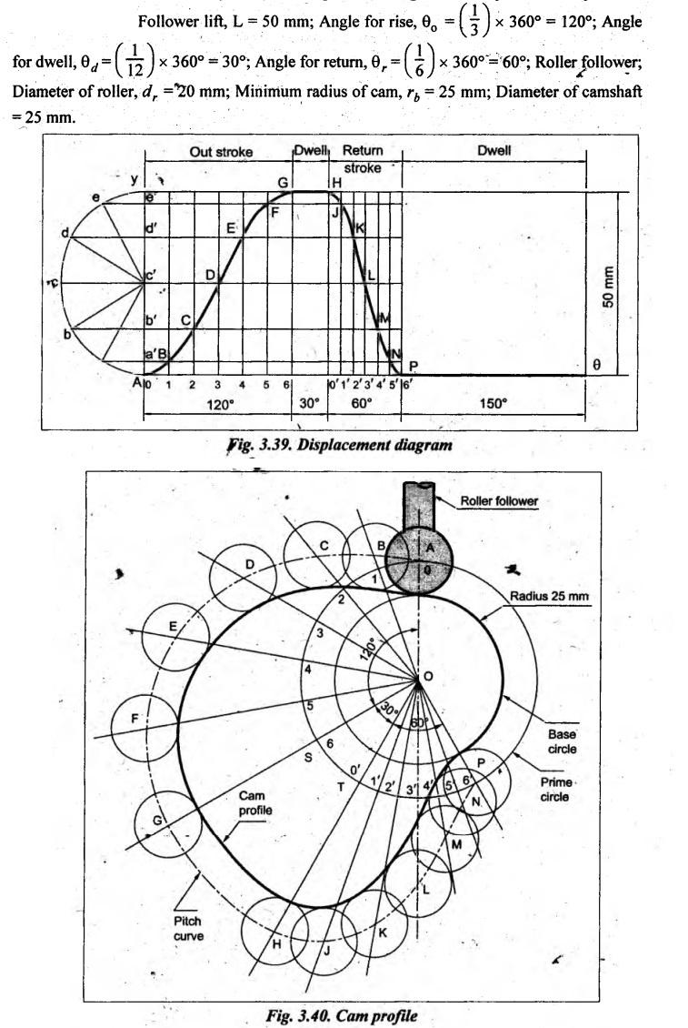
Solution: Construction of
displacement diagram: Since the follower is moving with SHM during both
outward and return strokes, therefore draw the displacement diagram of the
follower, by assuming suitable scale, as explained in Section 3.7.1. The
displacement diagram so obtained is shown in Fig.3.39.
Profile of the cam
when the axis of follower passes through the axis of camshaft:
The
cam profile when the axis of the follower passes through the axis of the
camshaft is drawn, as shown in the Fig.3.40, using the same procedure discussed
in Example 3.8.
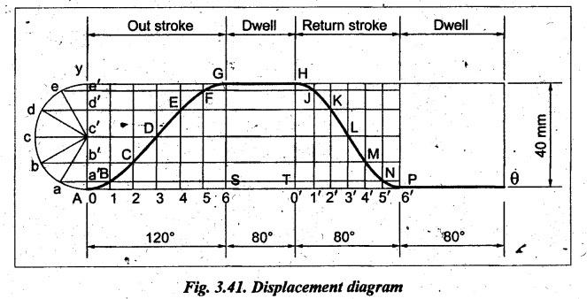
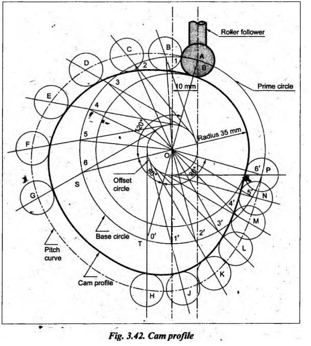
Example 3.9
The following data are for a disc cam mechanism with roller
follower: Minimum radius of the cam = 35 mm; Lift of the follower = 40 mm;
Offset of the follower = 10 mm right; Roller diameter = 15 mm.
Cam rotation angles are as mentioned below: During ascent =
120°; Dwell = 80°; During descent = 80°; Dwell = 80°. Cam rotates in clockwise
direction and the follower motion is simple harmonic during both ascent and
descent.
(i) Draw the displacement diagram of the follower and indicate
the relevant data.
(ii) Draw the cam profile and indicate the relevant data.
Given data:
Roller
follower; Minimum radius of cam, rb = 35 mm; Follower lift, L
= 40 mm; Offset10 mm; Diameter of roller, dr = 15 mm; Angle
for rise θ0 = 120°; Angle. for dwell, θd = 80°;
Angle for return, θr = 80°.
Solution: (i) ̧Construction
of displacement diagram: Since the follower is moving with SHM during
both outward and return strokes, therefore draw the displacement diagram of the
follower, by assuming suitable scale, as explained in Section 3.7.1. The
displacement diagram so obtained is shown in Fig.3.41.
(ii) Profile of the
cam when the axis of the follower is offset by 10 mm towards the right from the
cam axis:
The
cam profile when the axis of the follower is offset from the axis of the
camshaft is drawn, as shown in Fig.3.42, using the same procedure discussed in
Example 3.7.
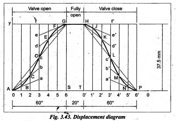
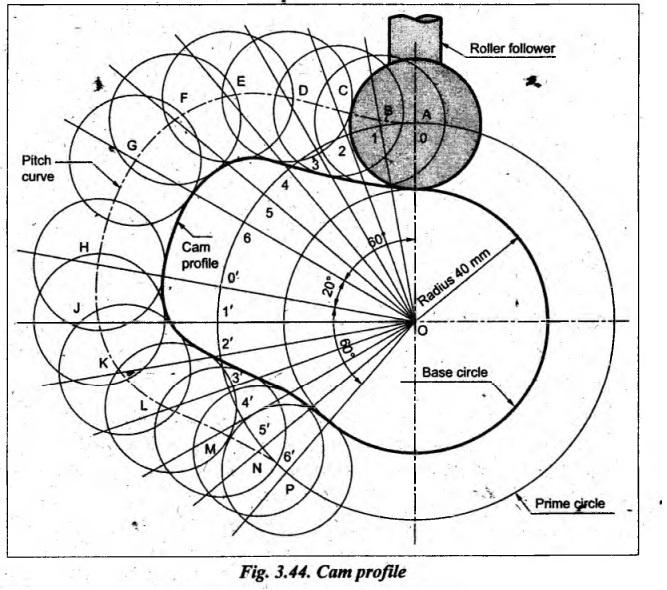
Example 3.10
Draw the profile of a cam for operating the exhaust valve of an
oil engine. It is required to give equal uniform acceleration and retardation
during opening and closing of the valve each of which corresponds to 60° of cam
rotation. The valve must remain in the fully open position for 20° of cam
rotation.
The lift of the valve is 37.5 mm and the least radius of the cam
is 40 mm. The follower is provided with a roller of radius 20 mm and its line
of stroke passes through the axis of the cam.
[A.U.,
Nov/Dec 2012]
Given data:
Angle
for rise, θ0 = 60°; Angle for dwell, θd = 20°;
Angle for return, θr = 60°; Follower lift, L = 37.5 mm; Least
rádius of cam, rb = 40 mm; Roller follower; Radius of ́roller, rr = 20 mm.
Solution: Construction of
displacement diagram: Since the follower is moving with UARM during
both outward and return strokes, therefore draw the displacement diagram of the
follower, by assuming suitable scale, as explained in Section 3.8.1. The
displacement diagram so obtained is shown in Fig.3.43.
Profile of the cam
when the axis of follower passes through the axis of camshaft:
The
cam profile when the axis of the follower passes through the axis of the
camshaft is drawn, as shown in Fig.3.44, using the same procedure discussed in
Example 3.7.
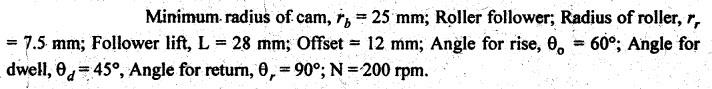
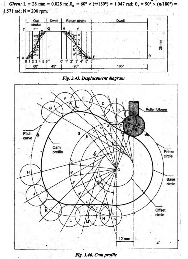
Example 3.11
The following data relate to a cam profile in which the follower
moves with uniform acceleration and deceleration during ascent and descent:
Minimum radius of cam = 25 mm
Roller radius Lift = 7.5 mm
Lift = 28 mm
Offset of follower axis = 12 mm towards right
Angle of ascent = 60°
Angle of descent = 90°
Angle of dwell between ascent and descent = 45°
Speed of the cam = 200 rpm
Draw the profile of the cam and determine the maximum velocity
and acceleration of the follower during the outstroke and return stroke.
Given data:
Solution: Construction of
displacement diagram: Since the follower is moving with UARM during
both outward and return strokes, therefore draw the displacement diagram of the
follower, by assuming suitable scale, as explained in Section 3.8.1. The
displacement diagram so obtained is shown in Fig.3.45.
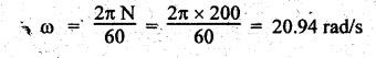
Profile of the cam
when the axis of the follower is offset by 12 mm towards the right from the cam
axis:
The
cam profile when the axis of the follower is offset from the axis of the
camshaft is drawn, as shown in Fig.3.46, using the same procedure discussed in
Example 3.7.
Maximum velocity and
acceleration of the follower during outward and return strokes:
We
know that angular velocity of the cam,
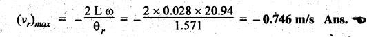
Maximum velocity of
follower during outward and return strokes:
We
know that maximum velocity of follower having UARM during outward stroke,
and
maximum velocity of follower having UARM during return stroke,
Maximum acceleration
of follower during outward and return strokes:
We
know that maximum acceleration of follower having UARM during outward strokes,
and
maximum acceleration of follower having UARM during return stroke,
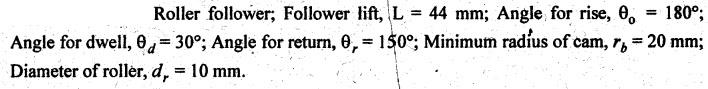
Example 3.12
Draw the profile of the cam when the roller follower moves with cycloidal
motion as given below:
(a) Outstroke with maximum displacement of 44 mm during 180° of
cam rotation. (b) Return stroke for the next 150° of cam rotation.
(c) Dwell for the remaining 30° of cam rotation.
The minimum radius of the cam is 20 mm and the diameter of the
roller is 10 mm. The axis of the roller follower passes through the camshaft
axis.
[A.U.,
May/June 2007]
Given data:
Solution:
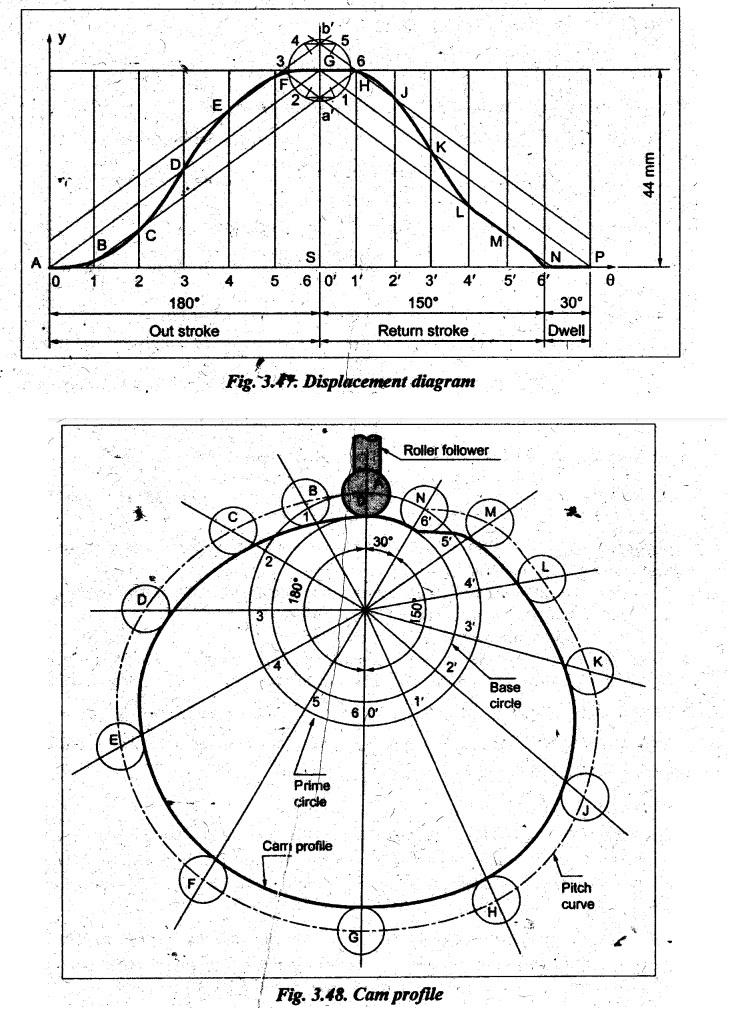
Construction
of displacement diagram: Since the follower is
moving with cycloidal motion during both outward and return
strokes, therefore draw the displacement diagram of the follower, by assuming
suitable scale, as explained in Section 3.9.1. The displacement diagram so
obtained is shown in Fig.3.47.
Profile of the cam
when the axis of follower passes through the axis of camshaft:
The
cam profile when the axis of the follower passes through the axis of the
camshaft is drawn, as shown in Fig.3.48, using the same procedure discussed in
Example 3.7.
Example 3.13
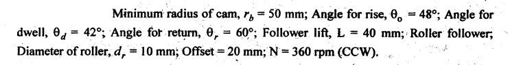
From the following data, draw the profile of the cam in which
the follower moves with SHM during ascent while it moves with uniformly
accelerated motion during descent: Least radius of cam = 50 mm; Angle of ascent
= 48°; Angle of dwell between ascent and descent 42°; Angle of descent 60°;
Lift of follower = 40 mm; Diameter of roller = 30 mm; Distance between the line
of action of the follower and the axis of cam = 20 mm.
If cam rotates at 360 rpm clockwise, find the maximum velocity
and acceleration of the follower during descent.
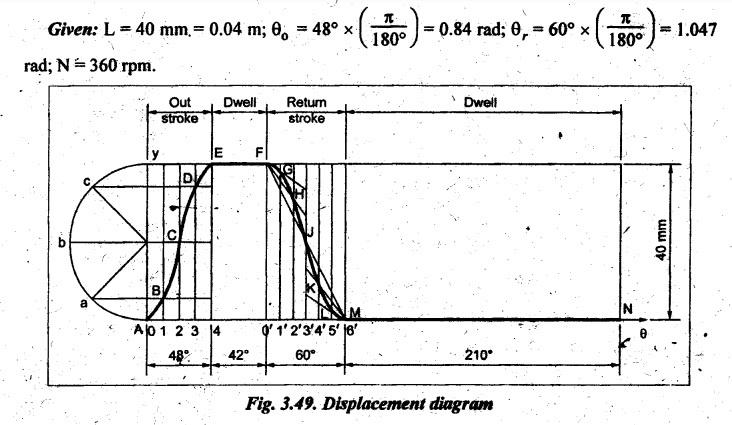
Given data:
Solution: Construction of
displacement diagram: For forward stroke, since the follower is moving
with SHM, the displacement diagram is drawn as shown in Fig.3.49, by assuming
suitable scale, as explained in Section 3.7.1. Similarly, for return stroke,
since the follower is moving with uniform acceleration and retardation
motion (UARM), the displacement diagram is drawn in Fig.3.49, as
explained in Section 3.8.1. The complete displacement diagram so obtained is
shown in Fig.3.49.
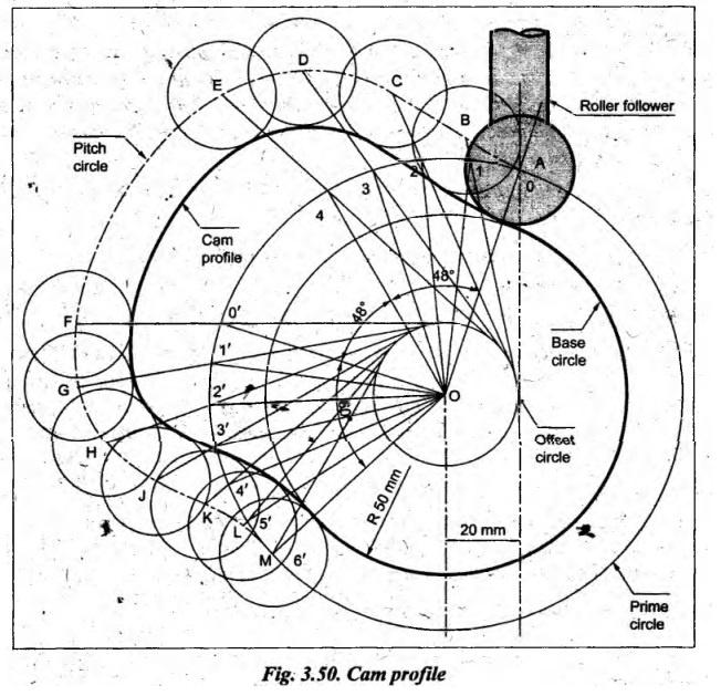
Profile of the cam
when the axis of the follower is offset by 20 mm from the cam axis:
The
cam profile when the axis of the follower is offset from the axis of the
camshaft is drawn, as shown in the Fig.3.50, using the same procedure discussed
in Example 3.7.
Maximum velocity and
acceleration of the follower during descent:
We
know that angular velocity of the cam,
Maximum
velocity of the follower having UARM during return stroke,
and
maximum acceleration of the follower having UARM during return stroke,
Example 3.14
A roller follower cam with a roller diameter of 10 mm is
rotating clockwise. The lift of the cam is 30 mm and the axis of the follower
is offset to the right by a distance of 5 mm. The follower completes the lift
with SHM during 120° of cam rotation. The dwell at lift is 60° of cam rotation.
First half of the fall takes place with constant velocity and second half with
constant acceleration and retardation during 120° of the cam rotation. The rest
is the dwell at fall. Draw the cam profile giving details of construction and
dimensions.
Given data:
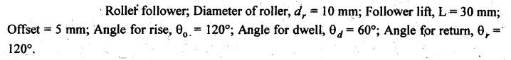
Solution: Construction of
displacement diagram: For forward stroke, since the follower is moving
with SHM, the displacement diagram is drawn as shown in Fig.3.51,
by assuming suitable scale, as explained in Section 3.7.1. Similarly, for
return stroke, since the follower is moving with uniform velocity motion
for first halt and with UARM for second half, the displacement diagram is drawn
in Fig.3.51, as explained in Section 3.6.1 and 3.8.1. The complete displacement
diagram so obtained is shown in Fig.3.51.
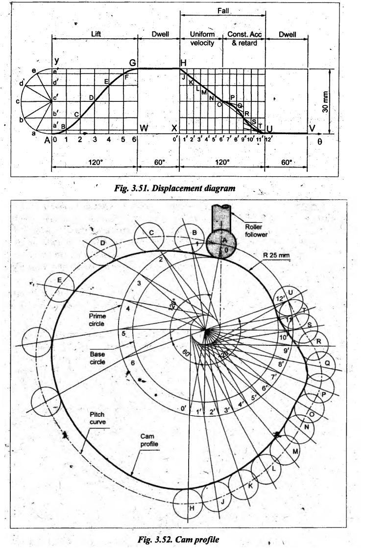
Profile of the cam
when the axis of the follower is offset by 5 mm from the cam axis:
The
cam profile when the axis of the follower is offset from the axis of the
camshaft is drawn, as shown in the Fig.3.52, using the same procedure discussed
in Example 3.5
Theory of Machines: Unit I: Kinematics of Mechanisms : Tag: : Kinematics of Mechanisms - Theory of Machines - synthesis of cam profile
Related Topics
Related Subjects

Theory of Machines
ME3491 4th semester Mechanical Dept | 2021 Regulation | 4th Semester Mechanical Dept 2021 Regulation