Engineering Mechanics: Unit I: Statics of Particles
Solved Example & Practice Problems: Equilibrium, Concurrent Force System in Three Dimensions
Examples for Practice: Statics of Particles - Engineering Mechanics
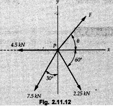
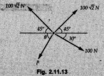
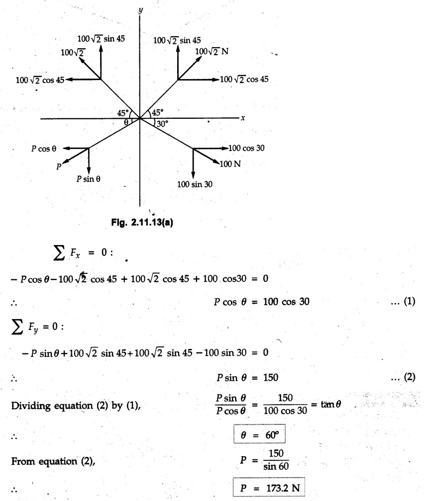
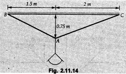
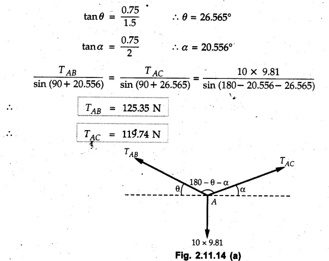
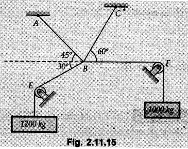
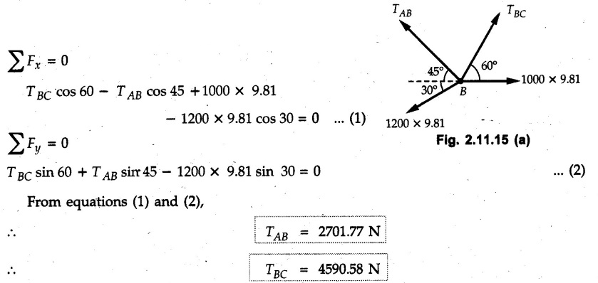
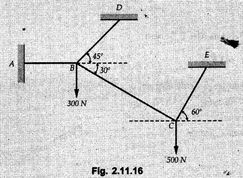
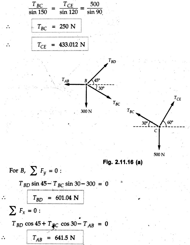
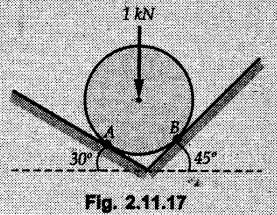
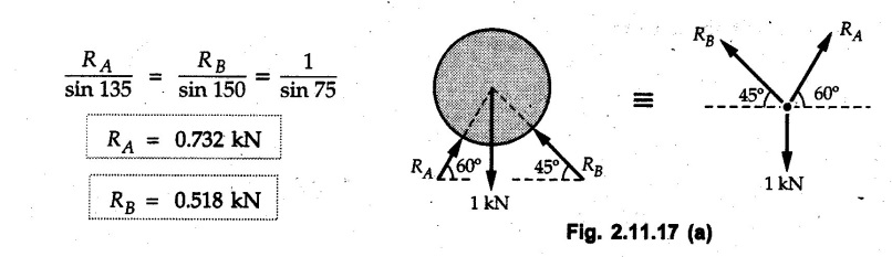
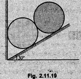
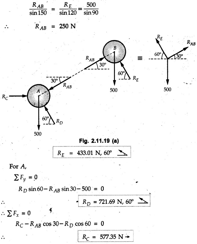
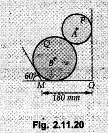
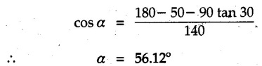
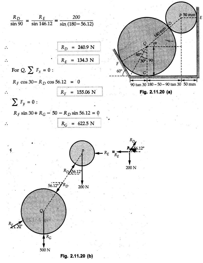
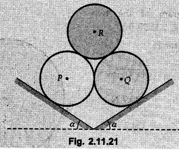
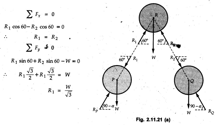
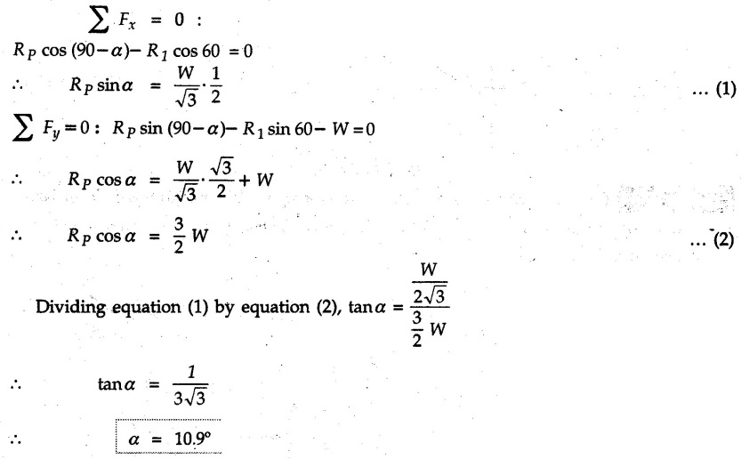
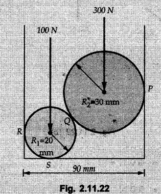
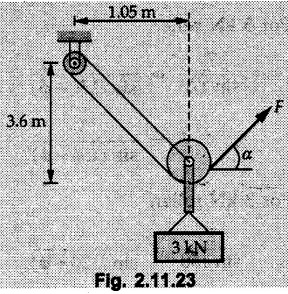
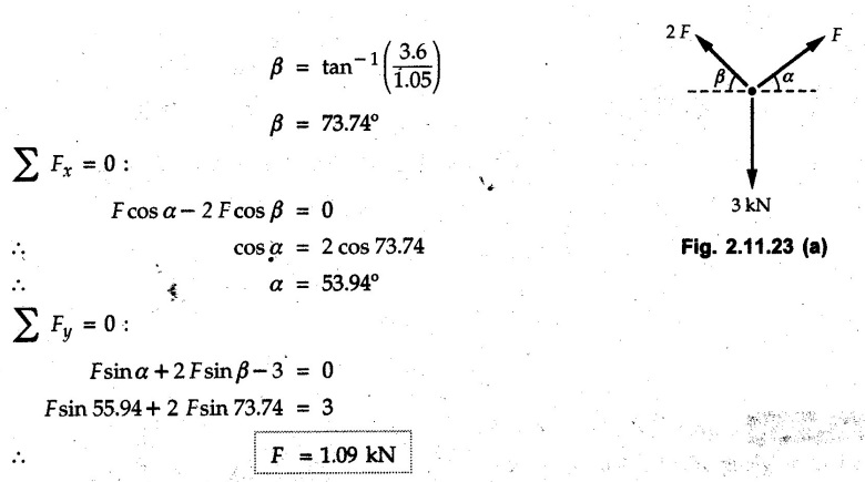
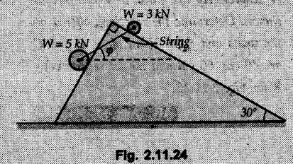
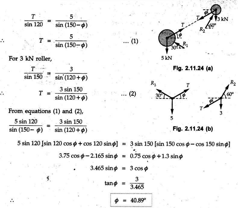
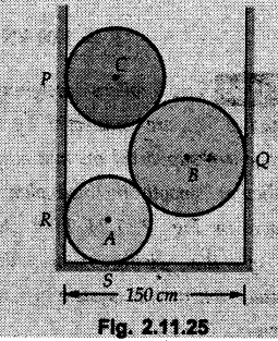
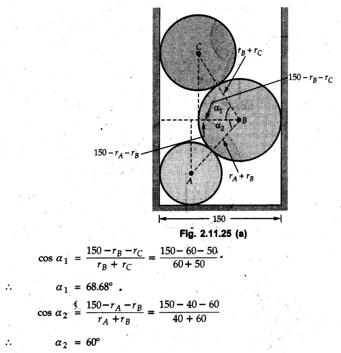
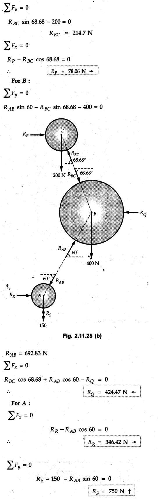
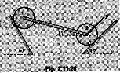
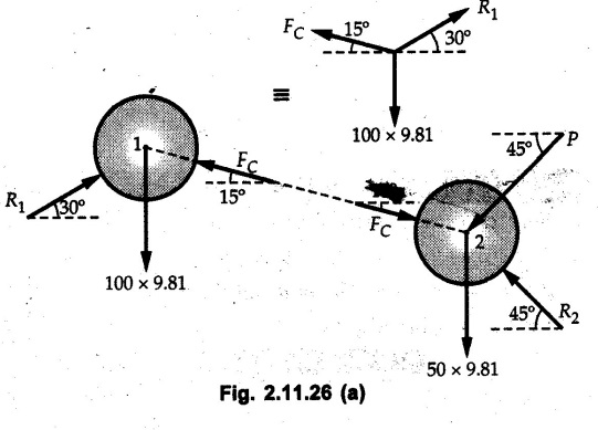
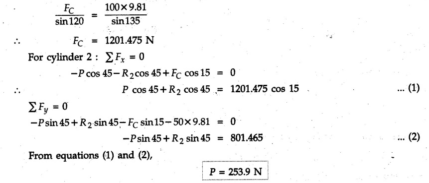
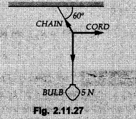
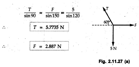
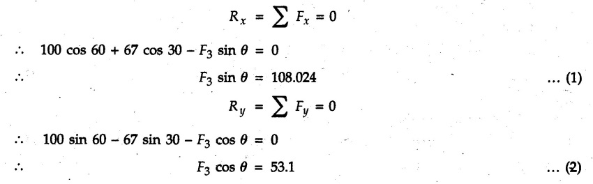
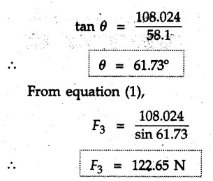
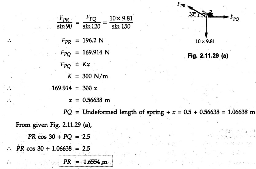
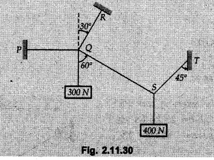
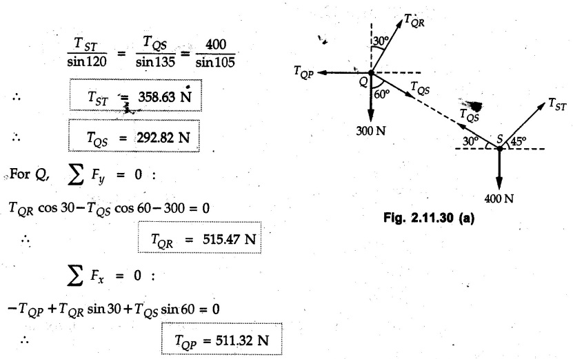
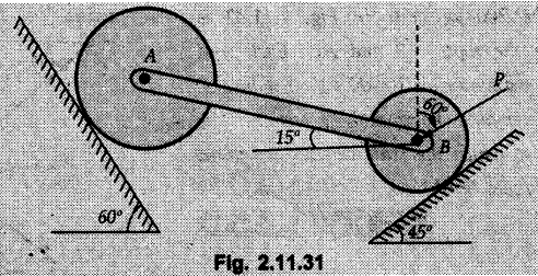
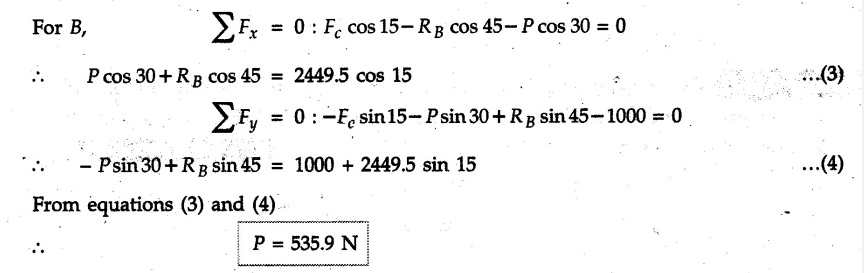
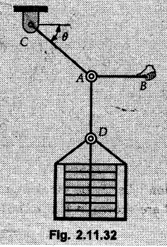
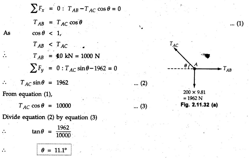
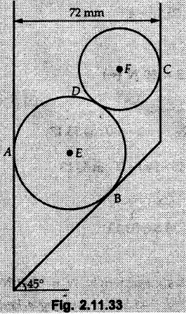
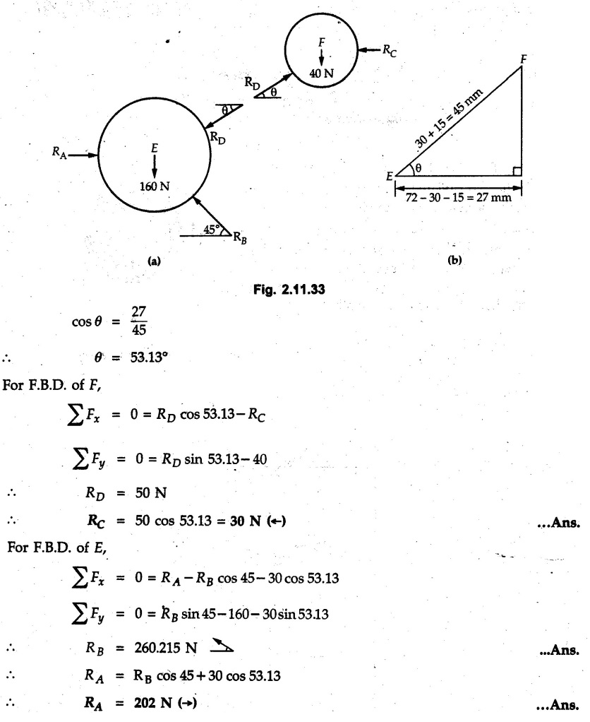
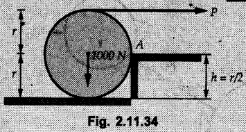
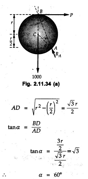
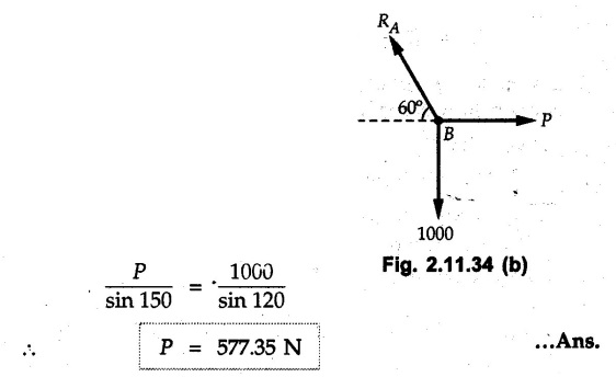
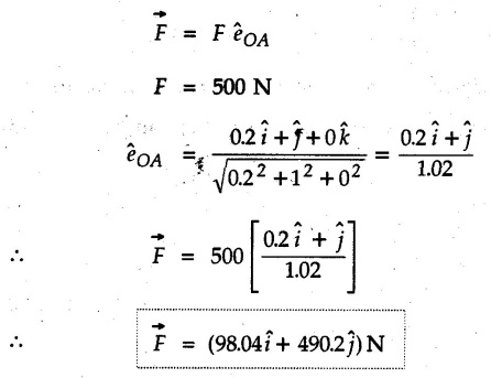
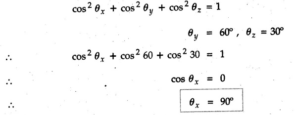
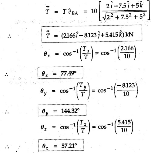
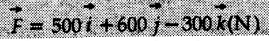
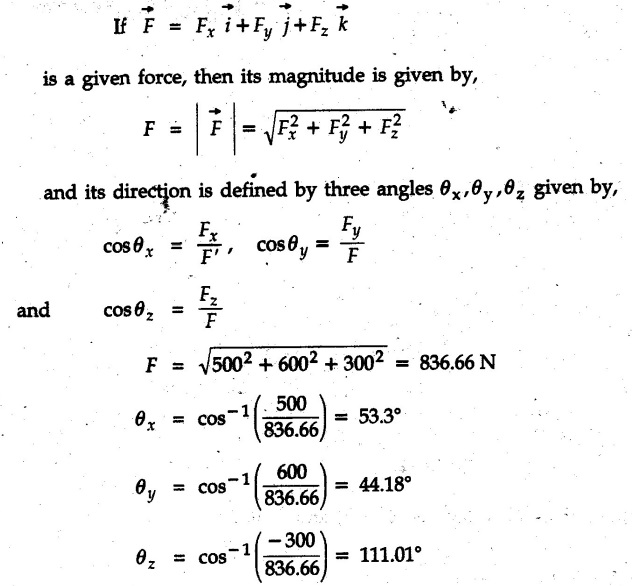
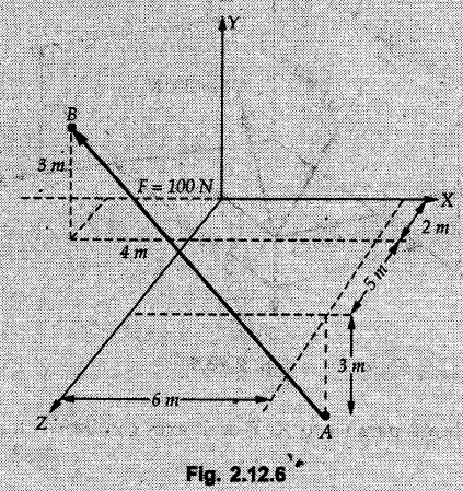
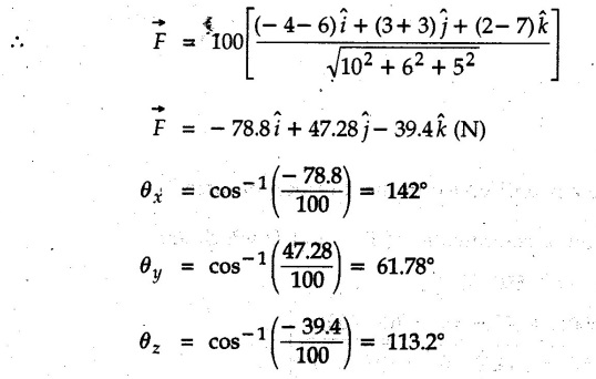
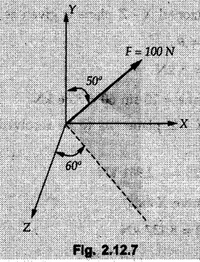
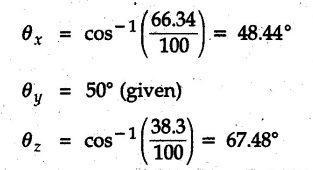
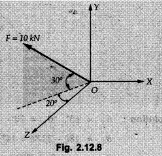
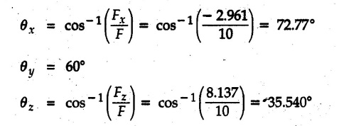
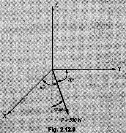
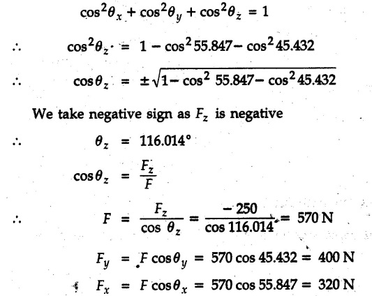
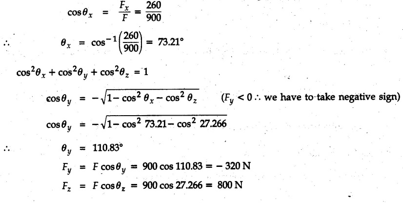
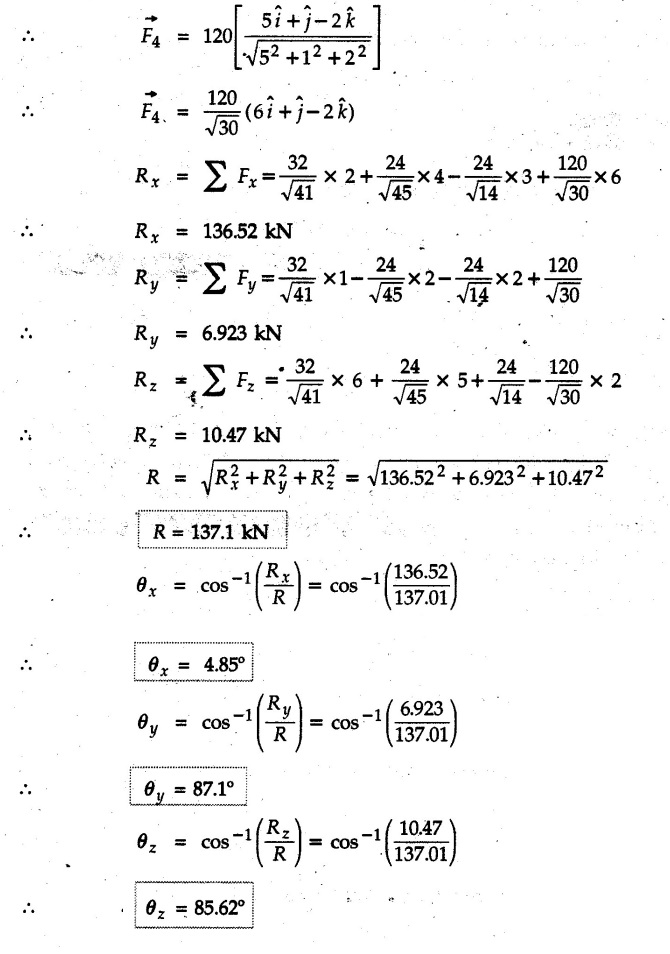
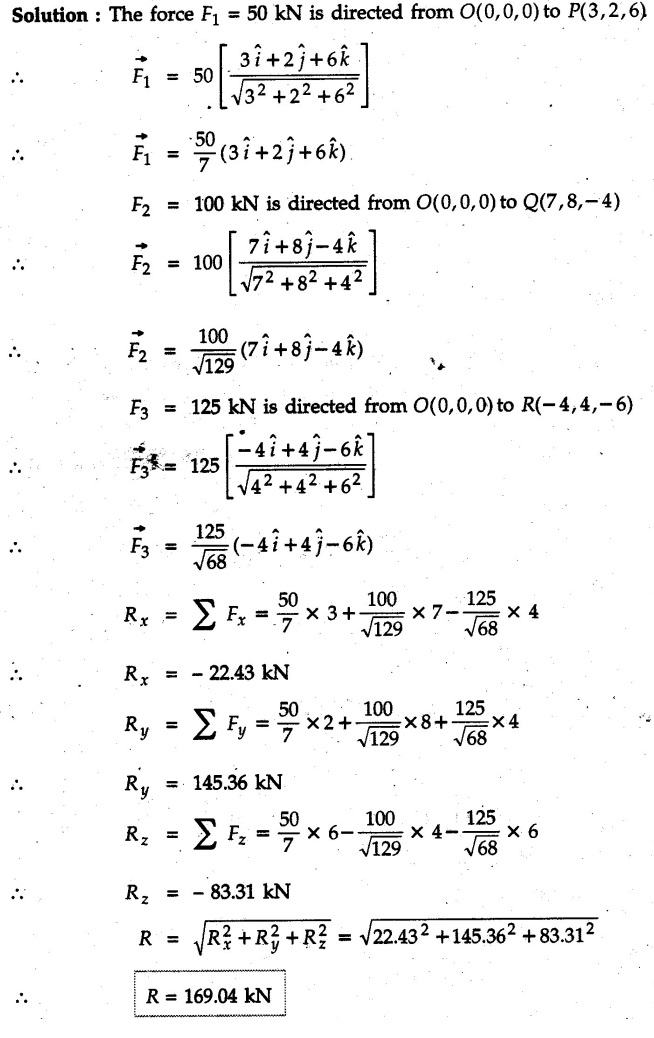
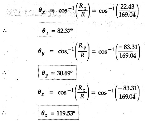
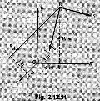
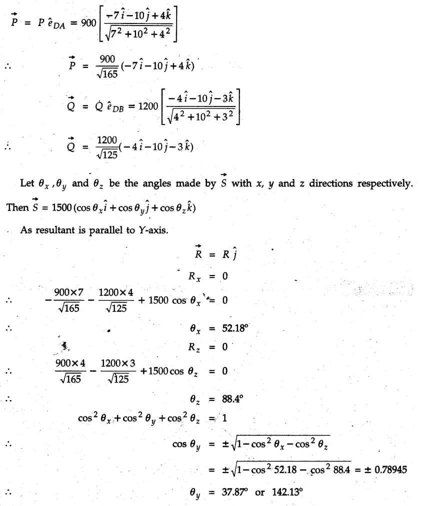
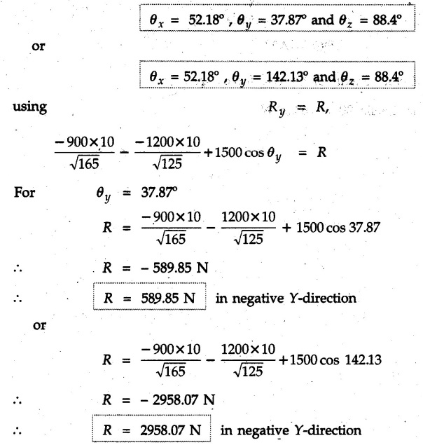
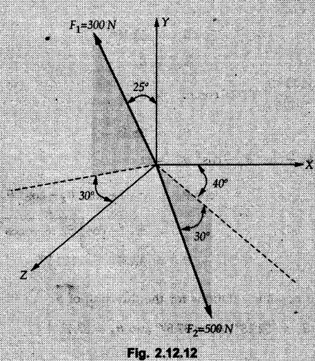
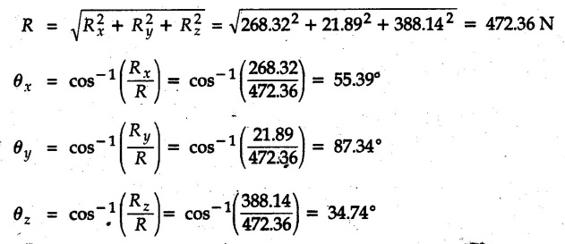
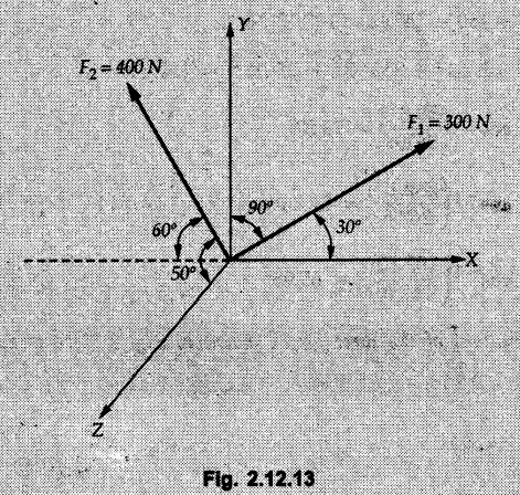
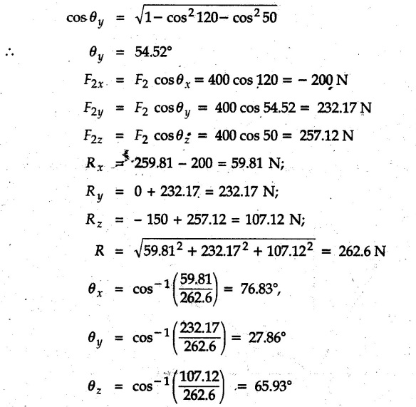
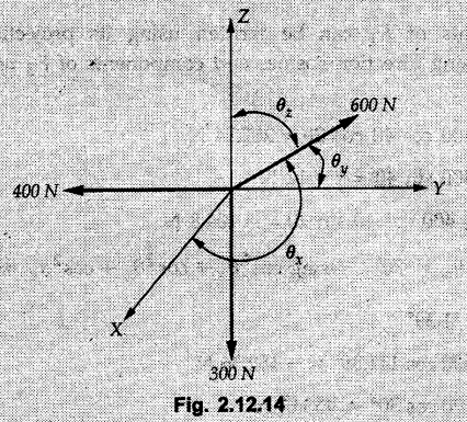
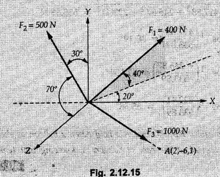
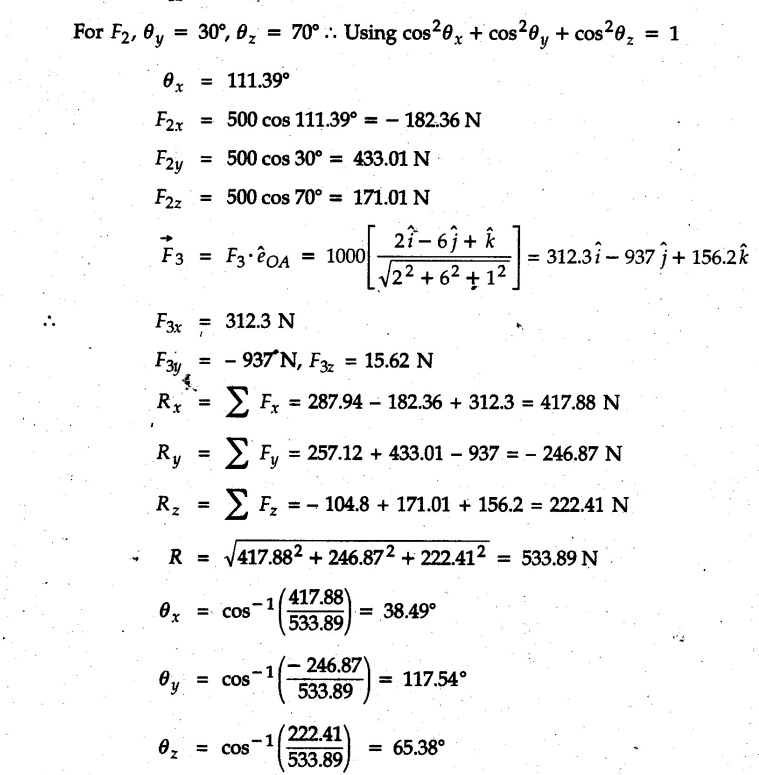
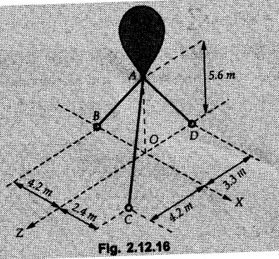
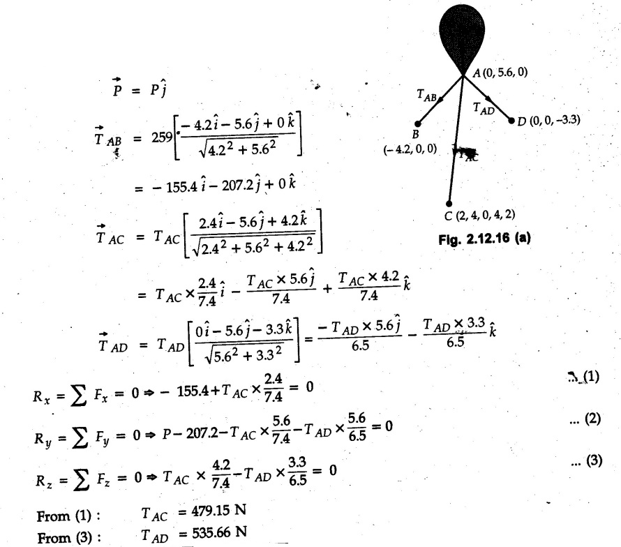
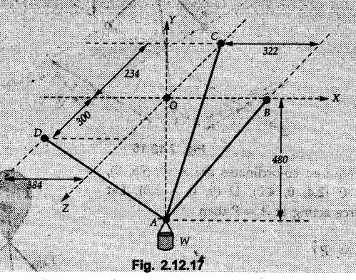
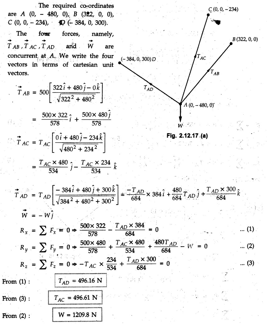
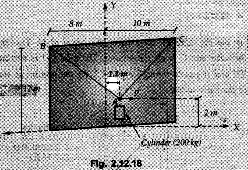
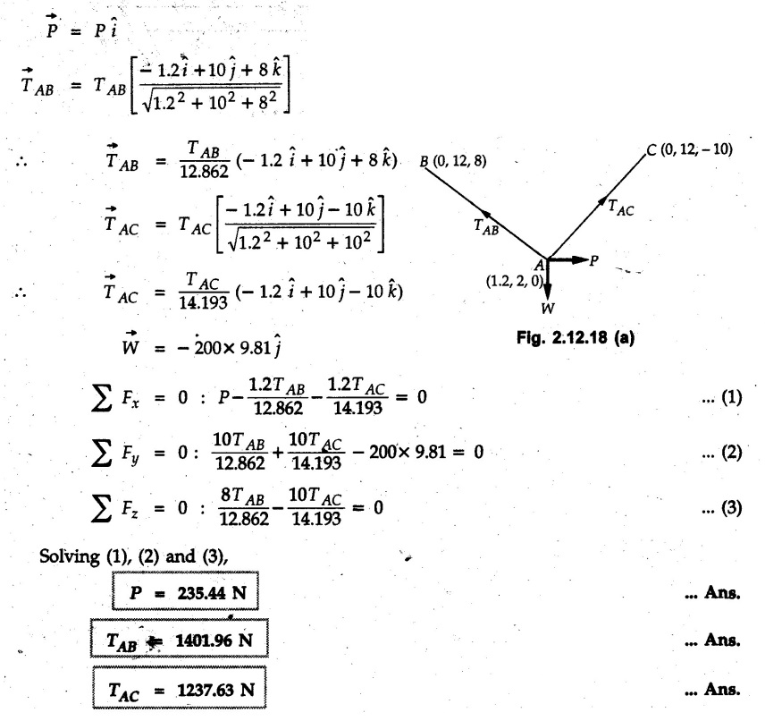
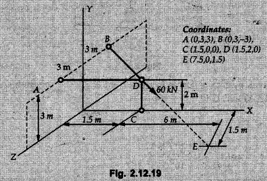
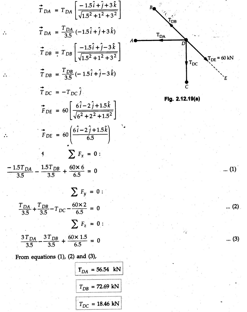
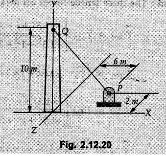
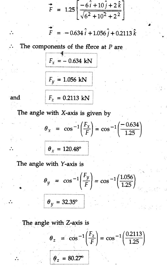
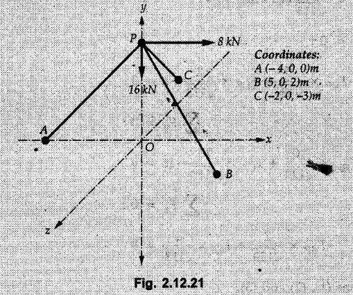
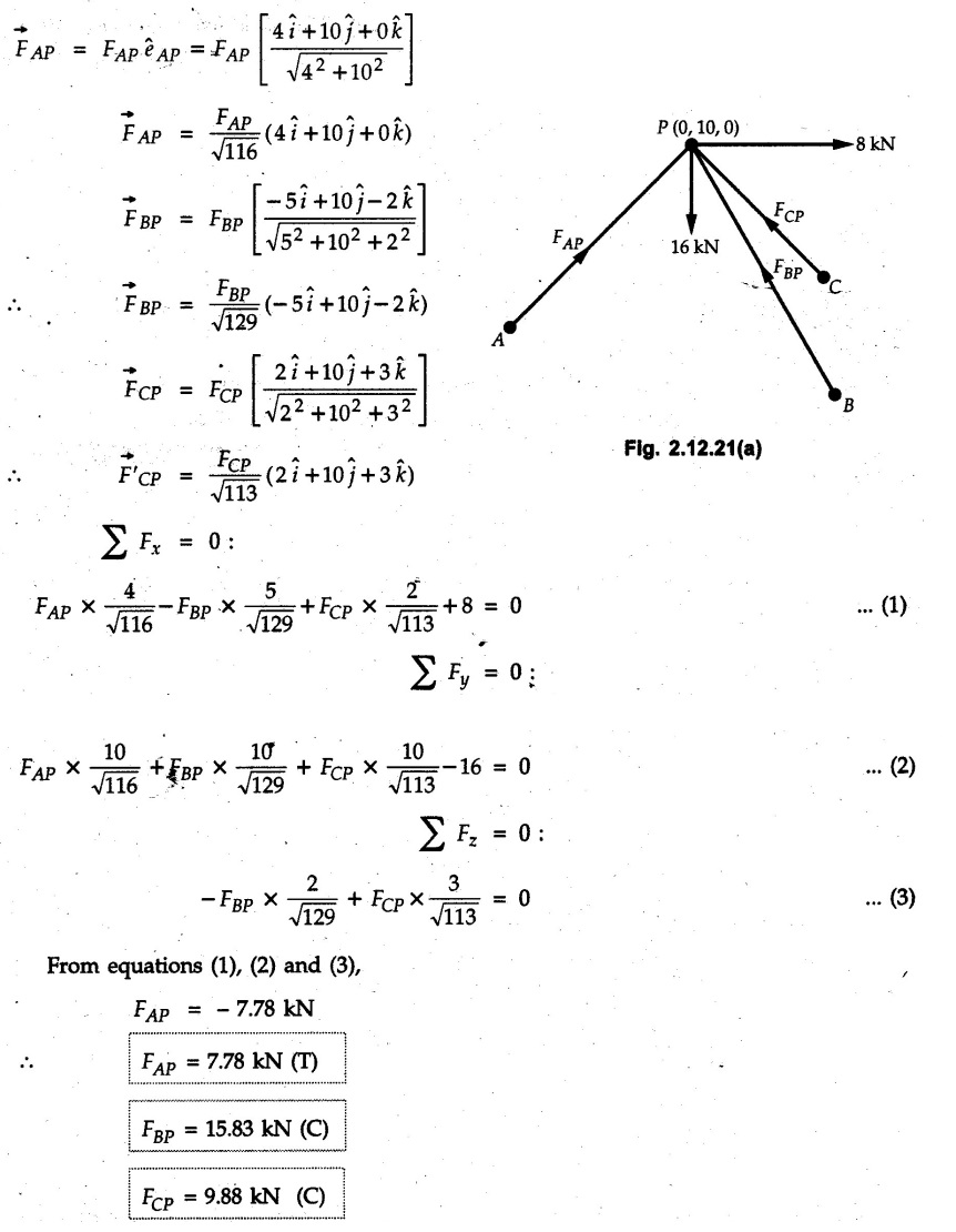
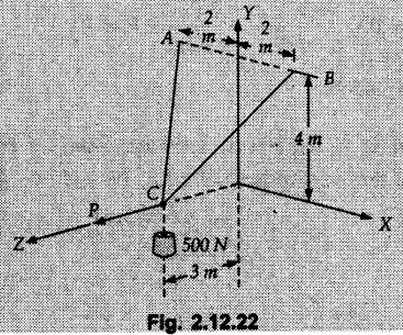
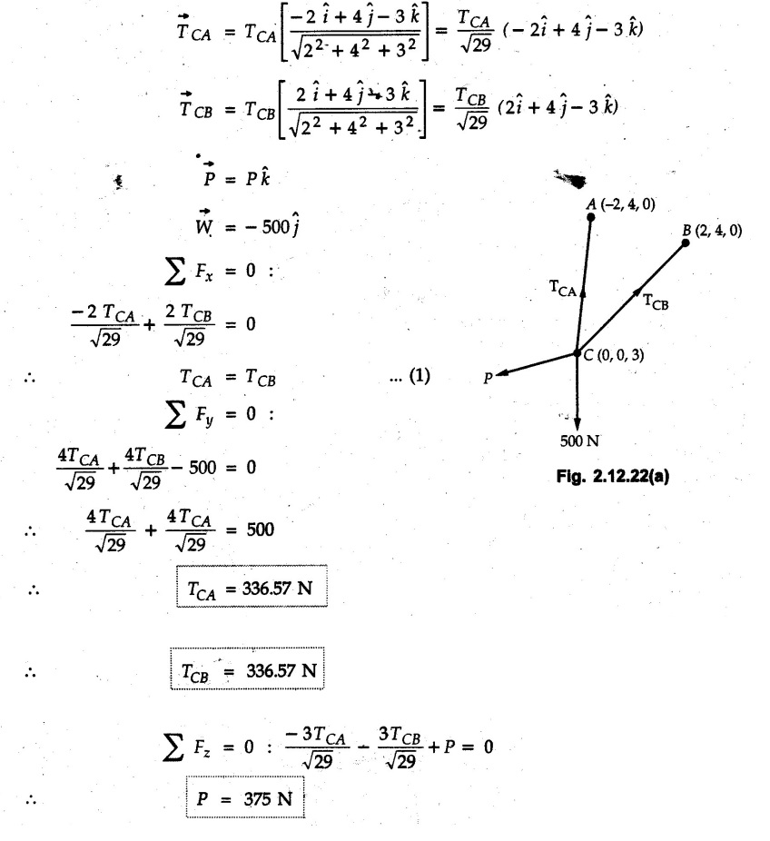
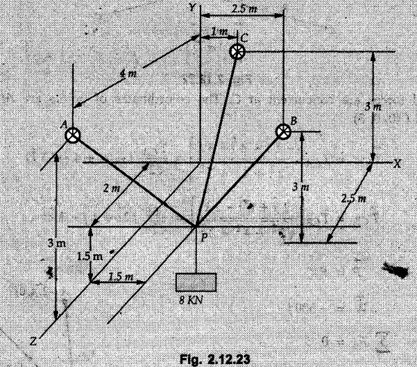
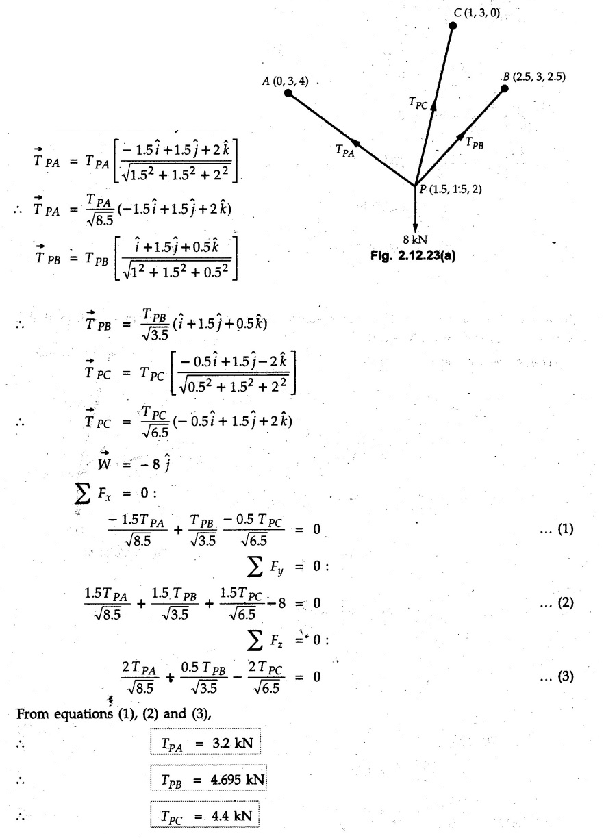
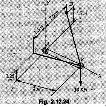
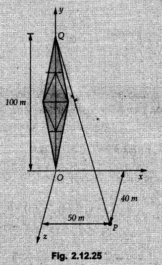
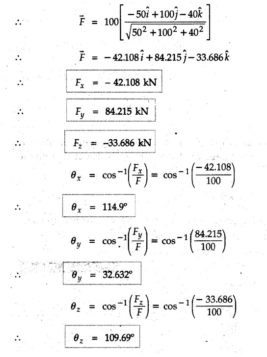
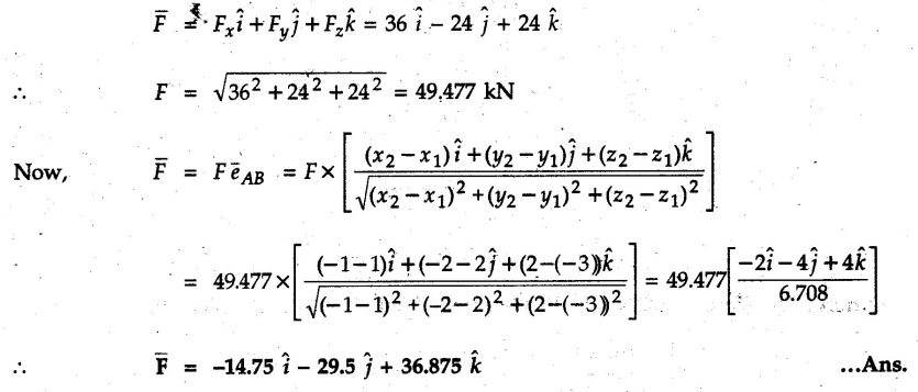
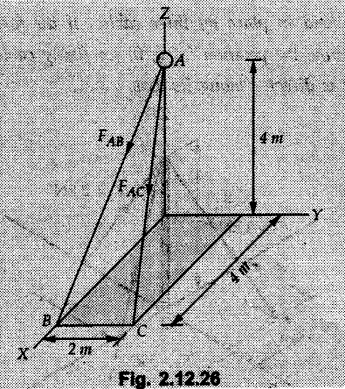
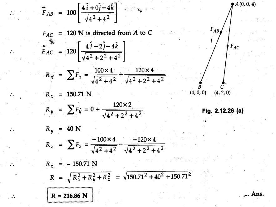
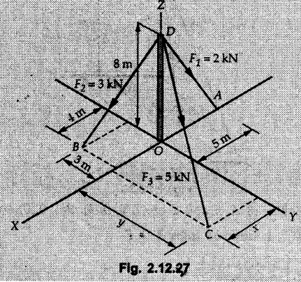
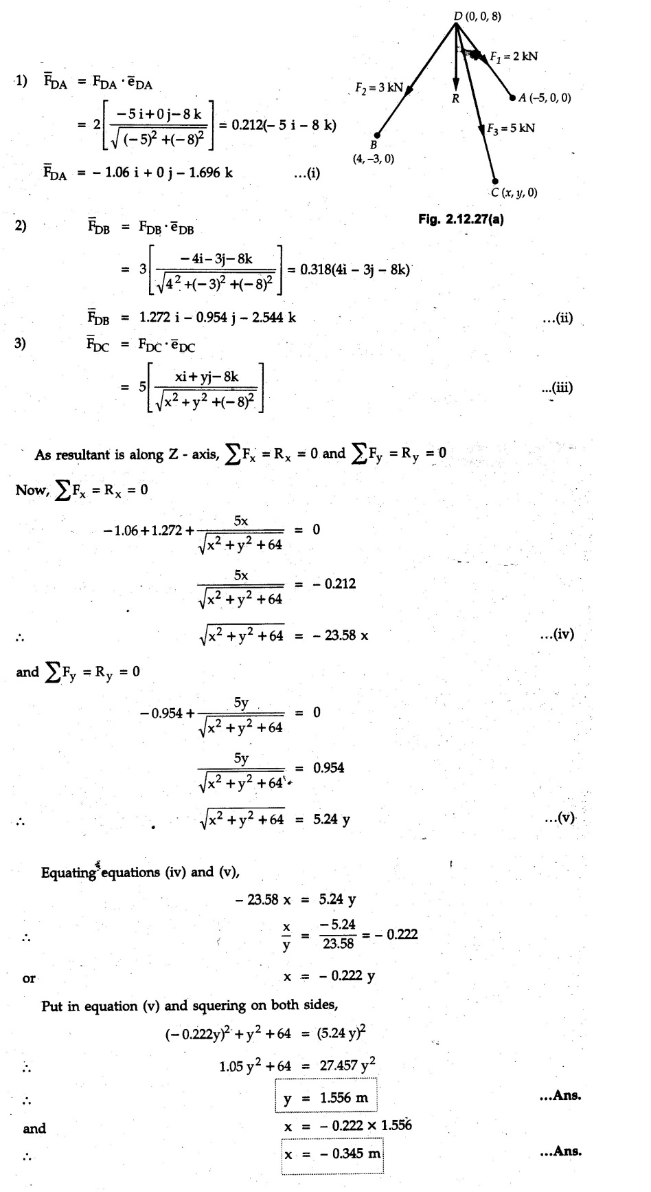
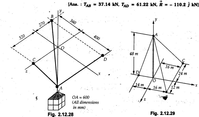
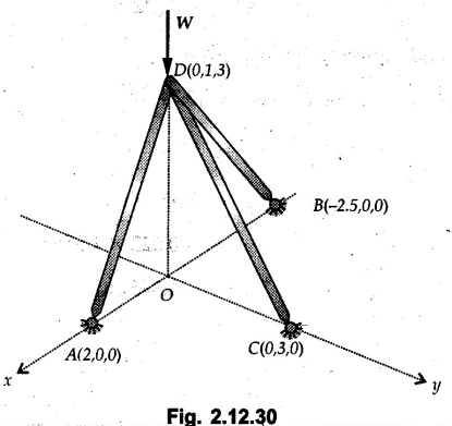
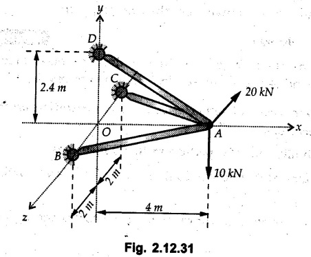
Example 2.11.1 Determine the magnitude and angle θ of F so that particle P, shown in Fig. 2.11.12 is in equilibrium. Solution : Example 2.11.2 Determine the magnitude and direction of the force 'P' which keeps the concurrent system in equilibrium (Fig. 2.11.13). Solution : Example 2.11.3 Fig. 2.11.14 shows a 10 kg lamp supported by two cables AB and AC. Find the tension in each cable. Solution: The F.B.D. of point A is shown in Fig. 2.11.14 (a). Using Lami's theorem, Example 2.11.4 Find the forces in cables AB and CB shown in Fig. 2.11.15. The remaining two cables pass Over frictionless pulleys E and F and support masses 1200 kg and 1000 respectively. Solution: All the forces are concurrent at B. The FBD of B is shown in Fig. 2.11.15 (a). Example 2.11.5 Fig. 2.11.16 shows a system of cables in equilibrium condition under two vertical loads of 300 N and 500 N. Determine the forces developed in the different segments. Solution: Free body diagrams of points B and C are shown in Fig. 2.11.16 (a). Using Lami's theorem for C, Example 2.11.6 Draw the freebody diagram of sphere shown in Fig. 2.11.17 and determine the reactions at the points of contact using Lami's theorem. Solution: The F.B.D. of sphere is shown in Fig. 2.11.17 (a). Using Lami's theorem, Example 2.11.7 Determine the tension in the string and the reaction at the contact surface for the cylinder of weight 1000 N placed as shown in Fig. 2.11.18. Solution: The F.B.D. of cylinder is shown in Fig. 2.11.18 (a). Using Lami's theorem, Example 2.11.8 Two identical rollers, each of weight 500 N, are supported by an inclined plane making an angle of 30° to the horizontal and a vertical wall as shown in the Fig. 2.11.19. i) Sketch the free body diagrams of the two rollers. ii) Assuming smooth surfaces, find the reactions at the support points. Solution: The F.B.D. of each roller is shown in Fig. 2.11.19 (a). The reaction between the two rollers makes angle 30° with horizontal as the line joining the centres is parallel to the inclined plane. For B, using Lami's theorem, Example 2.11.9 Two cylinder P and Q rest in channel as shown in the Fig. 2.11.20. The cylinder P has diameter of 100 mm and weighs 200 N where as the cylinder Q has diameter of 180 mm and weighs 500 N. If the bottom width $ 500 N. If the bottom width of the box is 180 mm, with one side vertical and other inclined at 60°, determine the reactions at all the four points of contact. Solution : To find the angle made by the reaction between P and Q with horizontal, use constructions as shown in Fig. 2.11.20 (a). The free body diagram of the two cylinders are shown in Fig. 2.11.20 (b). Using Lami's theorem for P, Example 2.11.10 Three identical spheres P, Q, R of weight 'W' are arranged on smooth inclined surfaces as shown in Fig. 2.11.21. Determine the angle 'α' which will prevent the arrangement from collapsing. Solution: The free body diagrams of the three spheres are as shown in Fig. 2.11.21 (a). When the arrangement is about to collapse, P and Q tend to move away from each other. As a result, reaction between P and Q tends to zero. From FBD of R: From FBD of P : Example 2.11.11 Determine the reactions at contact points for the system shown in Fig. 2.11.22. Solution: The reaction between the two rollers at Q is along the line joining their centres. The angle for this reaction with horizontal can be obtained as shown in Fig. 2.11.22 (a). cos α = 40/50 ⸫ α = 36.87° The free body diagrams of the two rollers are shown in Fig. 2.11.22 (b). Using Lami's theorem for F.B.D. of B, Example 2.11.12 A 3 kN crate is to be supported by the rope and pulley arrangement shown in Fig. 2.11.23. Determine the magnitude and direction of the force F, which should be exerted at the free end of the rope. Solution: The F.B.D of movable pulley is shown in Fig. 2.11.23 (a). From given Fig. 2.11.23, Example 2.11.13 Two rollers weighing 5 kN and 3 kN are connected by a string and are supported on mutually perpendicular smooth inclined planes as shown in Fig. 2.11.24 Find the angle of the string with the horizontal, when the system is in equilibrium. Solution: The FBDs of the rollers are shown in Fig. 2.11.24 (a). The forces are drawn away from the centre as shown in Fig. 2.11.24 (b) for using Lami's theorem. For 5 kN roller, Example 2.11.14 Three cylinders A, B and C weighing 150 N, 400 N and 200 N respectively are piled in a channel as shown. Determine the reactions offered by the walls and floor. Radit of A, B and C are 40 cm, 60 cm and 50 cm respectively. Refer Fig. 2.11.25. Solution: The reactions between the cylinders are along the line joining their centres. The angles α1 and α2 made by these reactions with horizontal can be obtained from Fig. 2.11.25 (a). The FBD for the three cylinders are shown in Fig. 2.11.25 (b). For C: Example 2.11.15 Two cylinders of masses m1 = 100 kg and my = 50 kg are connected by a rigid bar of negligible weight hinged at each cylinder. The cylinders are resting on smooth inclined planes and are in equilibrium in the position shown under a force P. Determine the magnitude of force P. Refer Fig. 2.11.26. Solution: The FBD of each cylinder is shown in Fig. 2.11.26 (a). The rigid bar is subjected to forces only at the ends and hence the force in it will be axial. As the tends length of bar to R1 130° decrease, there will be compressive force Fc in it which is directed towards the cylinders as shown. For cylinder 1 by Lami's theorem, Example 2.11.16 A lamp weighting 5 N is suspended from the ceiling by a chain. It is pulled aside by horizontal cord until the chain makes an angle of 60° with the ceiling as shown in Fig. 2.11.27 cord is horizontal as shown in Fig. 2.11.27. Find the tensions in the chain and the cord by applying Lami's theorem. Solution: The F.B.D. of point where force is applied, is shown in Fig. 2.11.27 (a). By Lami's theorem, Example 2.11.17 If the resultant of the three concurrent forces acting on the bolt shown in Fig. 2.11.28 is zero, determine the orientation of 0 and the required magnitude of F3. Solution : Dividing equation (1) by (2), Example 2.11.18 Find the length of cord PR in Fig. 2.11.29 so that the 10 kg bell is suspended in the position shown. The underformed length of the spring PQ is 0.5 m and the spring stiffness is 300 N/m. Solution: Using Lami's theorem for the F.B.D. of point P shown in Fig. 2.11.29 (a). Example 2.11.19 Determine the tensions in various segments of the connected flexible cables as shown in the Fig. 2.11.30. Solution: The free body diagrams of Q and S are shown in Fig. 2.11.30 (a) Using Lami's theorem for S, Example 2.11.20 Two cylinders, having weight WA = 2000 N and WB = 1000 N are resting on smooth inclined planes having inclination 60° and 45° with the horizontal respectively as shown in Fig. 2.11.31. They are connected by a weightless bar AB with hinge connections. The bar AB makes 15° angle with the horizontal. Find the magnitude of the force P required to hold the system in equilibrium. Solution: Let Fc be the compressive force in rod. The free body diagrams of cylinders A and B are shown in Fig. 2.11.31 (a) From equations (1) and (2), RA = 2732.05 N Fc = 2449.5 N Example 2.11.21 The 200 kg crate in Fig. 2.11.32 is suspended using the ropes AB and AC. Each rope can withstand a maximum of 10 kN before it breaks. If AB always remains horizontal, determine the smallest angle to which the crate can be suspended before one of the ropes breaks. Solution: The FBD of point A is shown in Fig. 2.11.32 (a). Example 2.11.22 Two cylinders E, F of diameter 60 mm and 30 mm. Weighing 160 N and 40 N respectively are placed as shown in Fig. 2.11.33. Assuming all the contact surfaces to be smooth, find the reactions at A, B and C. Solution: From Fig. 2.11.33 (b) Example 2.11.23 A roller of radius r and weight W = 1000 N is to be pulled over a curb of height h = r/2 as shown in Fig. 2.11.34 by applying a horizontal force P at the end of a string wound around the circumference of the roller. Find the magnitude of force P required to start the roller over the curb. Solution: The F.B.D. of roller is shown in Fig. 2.11.34 (a). To pull the roller over the curb, the reaction at the bottom surface tends to zero. As there are three forces acting on the roller, the direction of reaction at A must pass through the point of intersection of the lines of action of P and 1000 N. As RA has line of action from A to B, its angle a with horizontal will be given by, As the forces are concurrent at B as shown in Fig. 2.11.34 (b). Using Lami's theorem, Concurrent Force System in Three Dimensions Example 2.12.1 A force Solution : Example 2.12.2 A force of magnitude 500 N is passing through the origin and a point A (0.2, 1, 0) m. Write the vector form of the force. Solution : Example 2.12.3 Find the unit vector of the force Solution : Example 2.12.4 What is the inclination of a force with respect to the x axis if it is inclined at 60° with Y-axis and 30° with the Z-axis ? Solution : Example 2.12.5 The tension in the supporting cable AB is 10 kN as shown in Fig. 2.12.4. Write the force which the cable exerts on the beam BC as a vector Solution: The co-ordinates of A and B are: A (2, 0, 5) and B (0, 7.5, 0) Example 2.12.6 Determine the magnitude and direction of the force Solution: Example 2.12.7 Express the 5 forces shown in Fig. 2.12.5 as vectors in cartesian co-ordinates system. Solution : Forces which are parallel to X, Y or Z axes can be written directly in terms of Example 2.12.8 Express the 100 N force F shown in Fig. 2.12.6 as a vector in cartesian co-ordinate system and find its angles with X, Y and Z axes. Solution: The co-ordinates of A and B are A (6, 3, 7) and B (- 4, 3, 2). Example 2.12.9 Determine the X, Y and Z components of the 100 N force shown in Fig. 2.12.7. Also find the angles with the three co-ordinate axes. (See Fig. 2.12.7 on next page) Solution : As angle with Y-axis is 50°, Fy = 100 cos 50° = 64.28 N The components in X - Z plane will be 100 sin 50, which we have to resolve along X and Z direction. As angle with Z axis is 60o, Fz = (100 sin 50) × cos 60 Fz = 38.3 N and Fx = (100 sin 50) × sin 60 Fx = 66.34 N Example 2.12.10 Determine the X, Y and Z components of the 10 kN force shown in Fig. 2.12.8 and the angles with the three co-ordinate axes. Solution: Angle with the horizontal X - Z plane is given as 30°. ⸫ Angle with Y - axis = 60° = θy ⸫ Fy = 10 cos 60 = 5 kN The component in X- Z plane = 10 sin 60 = 8.66 kN This 5 kN component in X - Z plane has to be resolved in X and Z directions and angle with Z direction is 20°. ⸫ Fx = 8.66 sin 20 = 2.961 kN (X-components is on negative X-axis) Fz = 8.66 cos 20 = 8.137 kN Example 2.12.11 Determine the X, Y, Z components of the 500 N force shown in Fig. 2.12.9. Solution : θx = 65°, θy = 70° θz = 180 - 32.86 = 147.14 (θz is angle with positive Z-axis) Fx = F cos θx = 500 cos 65 = 211.31 N Fy = F cos θy = 500 cos 70 = 171 N Fz = F cos θz = 500 cos 147.14 = -420 N Example 2.12.12 A force acting at the origin of coordinate system has θx = 55.847° and θy = 45.432°. Knowing that the Z component of force is - 250 N, determine the angle θy, the other components of force and the magnitude of force. Solution: Example 2.12.13 A force F = 900 N acts at the origin of a coordinate system. If Fx = 260 N, θz = 27.266° and Fy < 0. Determine Fy, Fz, θx, and θy. Solution : Solved Examples for Understanding Example 2.12.14 Determine the resultant of the three concurrent forces Solution: Example 2.12.15 Forces 32 kN, 24 kN, 24 kN and 120 kN are concurrent at origin and are respectively directed through the points whose coordinates are A(2,1,6), B(4,- 2,5), C(-3,-2,1) and D(5,1,-2). Determine the magnitude of the resultant and the angles it makes with coordinate axes. Solution: F1 = 32 kN is directed from O(0,0,0) to A(2,1,6) F3 = 24 kN is directed from O(0,0,0) to C(-3,-2,1) F4 = 120 kN is directed from O(0,0,0) to D(5,1,-2) Example 2.12.16 A system of concurrent forces 50 kN, 100 kN and 125 kN act at a point O(0,0,0) and the forces are directed respectively through the points whose coordinates are P (3, 2, 6), Q (7, 8, 4) and R ( 4, 4, 6). Determine resultant and its direction. Solution: The direction of the resultant is defined by the three angles θx, θy and θz with the X, Y and Z axes respectively. Example 2.12.17 Three forces P = 900 N, Q = 1200 N and S = 1500 N act at a point O as shown in Fig. 2.12.11. The force P acts along the line DA, while Q acts along the line DB. Determine the direction of force S, so that the resultant of the three forces is parallel to Y-axis. What is the magnitude of the resultant force? Solution: The co-ordinates of points are as follows: D (4, 10, 0), A (− 3, 0, 4), B(0, 0, – 3) Thus there are two possible solutions for the direction of Example 2.12.18 Find the magnitude and direction of resultant of the two forces shown in Fig. 2.12.12. Solution: The X, Y and Z components of the two forces are F1x = 300 sin 25 sin 30 = – 63.39 N F1y = 300 cos 25 = 271.89 N F1z = 300 sin 25 cos 30 = 109.8 N F2x = 500 cos 30 cos 40 = 331.71 N F2y = - 500 sin 30 = - 250 N F2z = 500 cos 30 sin 40 = 278.34 N Rx = F1x + F2x = -63.39 + 331.71 = 268.32 N Ry = Fly + F2y = 271.89 - 250 = 21.89 N Rz = F1z + F2z = 109.8 + 278.34 = 388.14 N Example 2.12.19 Find the magnitude and direction of resultant of the two forces shown in Fig. 2.12.13. Solution: F1 = 300 N makes 90° angle with Y-axis. Hence it lies in X-Z plane. As it makes 30° angle with X axis, it will make 60° angle with negative Z-axis. ⸫ F1x = 300 cos 30 = 259.81 N Fly = 0 F1z = - 300 sin 30 = - 150 N For F2 = 400 N, θx = 180 - 60 = 120°, θz = 50°. (take positive sign as y component is positive) Example 2.12.20 Resultant of the three forces shown in Fig. 2.12.14 is zero. Find values of θx, θy, and θz. Solution: As resultant is zero, Rx = 0, Ry = 0 and Rz = 0 Rx = 0 ⇒ 600 cos θx = 0 ⸫ θx = 90° Ry = 0 ⇒ 600 cos θy – 400 = 0 θy = 48.19° Rz = 0 ⇒ 600 cos θz -300 = 0 θz = 60° Example 2.12.21 Find the magnitude and direction of resultant of the three forces shown in Fig. 2.12.15. Solution: Components of F1 can be written using its projection on X components of F2 using direction cosines and components of F3 using unit vector in the direction of force. Flx = 400 cos 40 cos 20 = 287.94 N Fly = 400 sin 40 = 257.12 N F1z = - 400 cos 40 sin 20 = - 104.8 N Example 2.12.22 Three cables AB, AC and AD hold down a balloon as shown in Fig. 2.12.16. Find vertical force exerted at the base of balloon A, knowing that tension in cable AB is 239 N. Solution: The required co-ordinates are A B (- 4.2, 0, 0), C (2.4, 0, 4.2), D (0, 0, magnitude of force acting at A = P then Example 2.12.23 Three cables support a load W as shown in Fig. 2.12.17 knowing that tension in cable AB is 500 N, find W. What will be magnitudes of tensions in AC and AD? Solution: Example 2.12.24 A 200 kg cylinder is hung by means of two cables AB and AC which are attached to the top corners B and C of a vertical wall. A horizontal force P perpendicular to the wall holds the cylinder 1.2 m away from the wall. Determine the value of P and the tension in the cables AB and AC. Solution: The given system of forces is concurrent at A. The required co-ordinates are A (1.2, 2, 0), B (0, 12, 8) and C (0, 12, 10). Example 2.12.25 In the Fig. 2.12.19, three wires are joined at D. Two ends A and B are on the wall and the other end C is on the ground. The wire CD is vertical. A force of 60 KN is applied at 'D' and it passes through a point E on the ground as shown in figure. Find the forces in all the three wires. Solution: The three tensile forces act away from D. Example 2.12.26 A metal guy rope tied to a peg at P shown in Fig. 2.12.20 keeps an electric post in equilibrium. The force in the guy rope is 1.25 kN. Find the components of the force at P and the angles of inclination of the force with the three rectangular axes. Solution: The coordinates of P and Q are P(6,0,-2) and Q(0,10,0) The force F of magnitude 1.25 kN is directed from P and Q. Example 2.12.27 Two forces act upon a tripod at 'P' as shown in Fig. 2.12.21. The force 8 kN is parallel to x-axis and the force 16 kN is parallel to y-axis. Determine the forces acting at the legs of tripod if the legs rest on ground at A, B and C whose coordinates with respect to O are given. The height of the P above the origin is 10 m. Solution: The coordinates of P are (0, 10, 0). The two given forces can be written as The forces in the legs of the tripod are assumed to be compressive. Considering all forces acting at P, these forces will be directed towards P, Example 2.12.28 A load of 500 N is to be held in equilibrium by means of two strings CA and CB and by a force P as shown in Fig. 2.12.22. Determine tensions in strings and magnitude of P. Solution All forces are concurrent at C. The co-ordinates of points are A(-2, 4, 0), B(2, 4, 0) and C(0, 0, 3). Example 2.12.29 A weight of 8 kN is suspended by means of three cables as shown in Fig. 2.12.23. Determine the forces in the cables PA, PB and PC. Solution: The co-ordinates of points required to write forces in vector form are as follows: A(0, 3, 4), B(2.5, 3, 2.5), C(1, 3, 0), P(1.5, 1.5, 2) Consider forces acting at point P. The tensile forces act away from P. Example 2.12.30 Determine the tension in cables BC and BD and the reactions at the ball and socket at A for the rod shown in Fig. 2.12.24 Solution: The force in rod AB is compressive. The co-ordinates of points are B (5, 0, 0), C(0, 1.25, 1.5) and D(0, 1.5, – 2.5). The forces are concurrent at B. The reaction at A equals the force in rod AB. As this force is compressive, the force in rod at A is directed along negative x-direction due to which reaction at A is directed in positive x-direction. Example 2.12.31 The guy wire a pole is anchored by means of a bolt at a point P as shown 2.12.25. The force in the wire is 100 kN. Determine i) The components of the force in the x, y and z-directions and ii) The direction of the force. Solution: The force of 100 kN is directed from P (50, 0, 40) to Q (0, 100, 0). Example 2.12.32 The x, y, z, component of a force are 36 kN, −24 kN and 24 kN respectively. Find the component of this force along the line joining A (1, 2, -3) and B(-1, -2, 2) Solution: Example 2.12.33 The cable exerts forces FAB = 100 N and FAC = 120 N on the ring at A as shown in Fig. 2.12.26. Determine magnitude of the resultant force acting at A. Solution: The co-ordiantes of A, B and C are A(0, 0, 4), B(4, 0, 0) and C(4, 2, 0) FAB = 100 N is directed from A to B Example 2.12.34 A pole is held in place by three cables. If the force of each cable acting on the pole is shown, determine the position (x, y, 0) for fixing cable DC so that the resultant force exerted on the pole is directed along its axis. Solution : Fig. 2.12.27 (a) shows different forces acting on the pole. Examples for Practice Q.1 A crate is supported by three cables as shown. Determine the weight of the crate if the tension in cable AB is 750 N. Refer Fig. 2.12.28. [Ans. : W = 2101.875 N} Q.2 Knowing that the tension in AC is, TAC = 20 kN, determine the required values of tension TAB and TAD so that the resultant of the three forces applied at A is vertical and calculate resultant. Refer Fig. 2.12.29. Q.3 A tripod supports load W as shown in Fig. 2.12.30 If force in leg AD is 3 kN compressive, find magnitude of W and forces in legs BD and CD. [Ans. : W = 6.49 kN, FBD = 2.586 kN, FCD = 2.6 kN] Q.4 Determine forces in members AB, AC and AD when the system of three members and two forces is in equilibrium. Loads 10 kN and 20 kN are parallel to y-axis and z-axis respectively. [Ans.: FAB = 13.044 kN(T), FAC = 31.68 kN(C). FAD = 19.44 KN(T)]Concept of Equilibrium
Solved Examples for Understanding


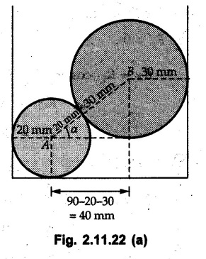
From Fig. 2.11.22 (a),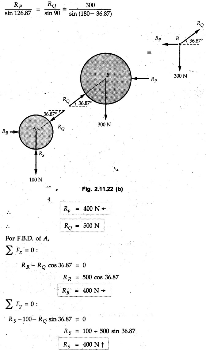


Solved Examples for Understanding
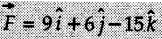 acts through the origin. What is the magnitude of the force and the angle it makes with X, Y, and Z axis?
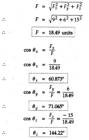
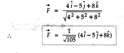
![]() . Determine the angles of
. Determine the angles of ![]() p forms with the positive x, y and z axis.
p forms with the positive x, y and z axis.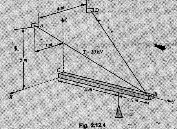
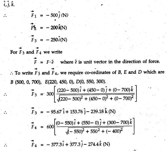
 The forces are in Newton.
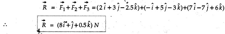

![]()


Engineering Mechanics: Unit I: Statics of Particles : Tag: : - Solved Example & Practice Problems: Equilibrium, Concurrent Force System in Three Dimensions
Related Topics
Related Subjects

Engineering Mechanics
ME3351 3rd semester civil, Mechanical Dept | 2021 Regulation | 3rd Semester Mechanical Dept 2021 Regulation