Manufacturing Technology: Unit V: Programming of CNC Machine Tools
solved anna university problems on part programing
Programming of CNC Machine Tools - Manufacturing Technology
solved anna university problems on part programing: Programming of CNC Machine Tools - Manufacturing Technology
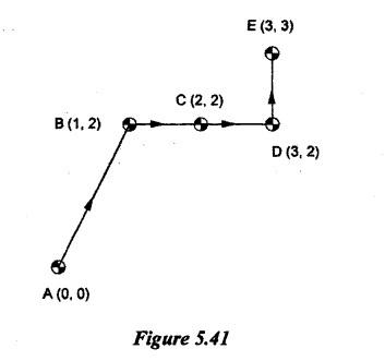
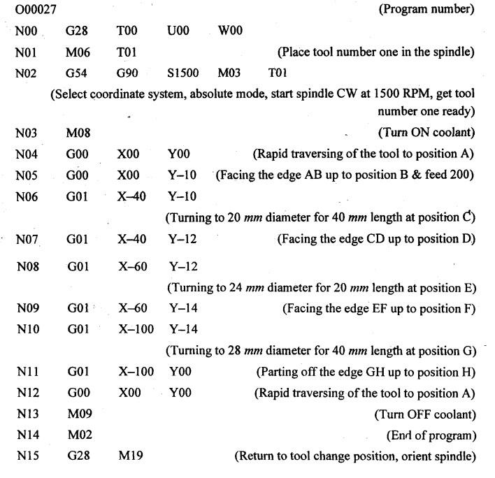
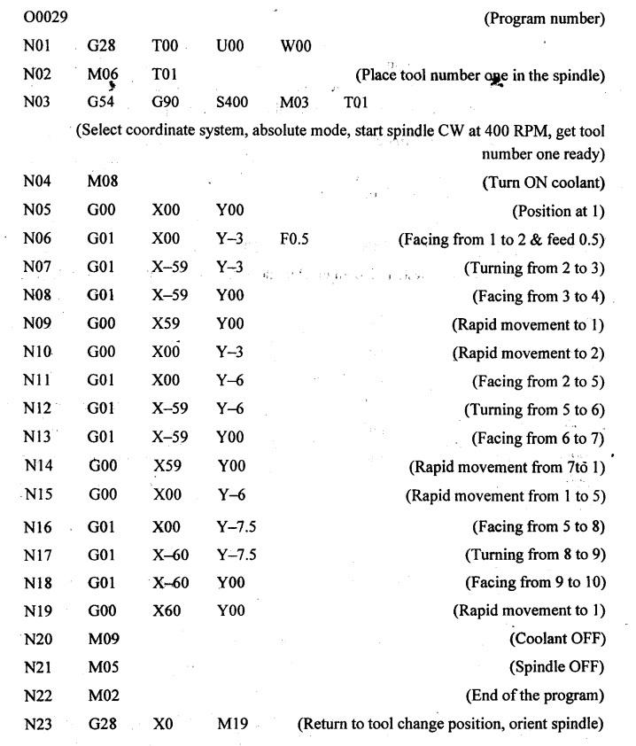
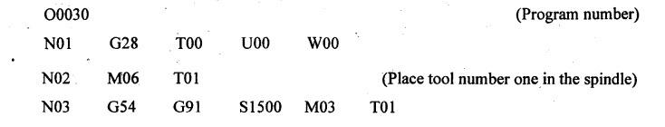
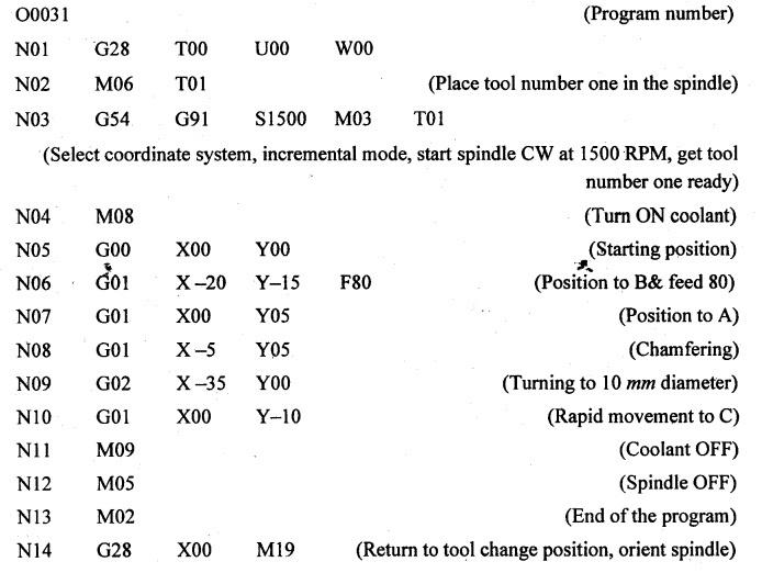
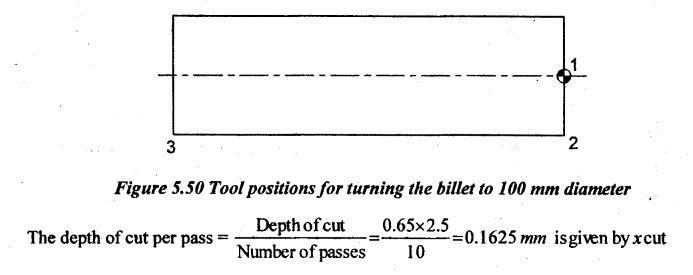
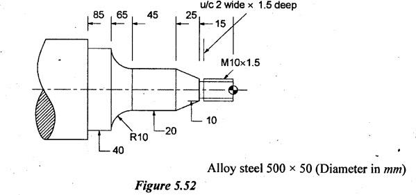
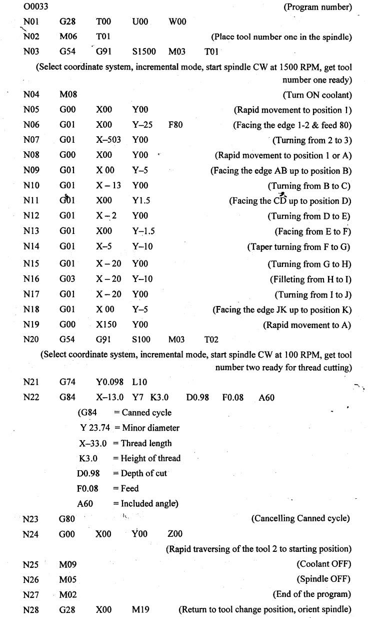
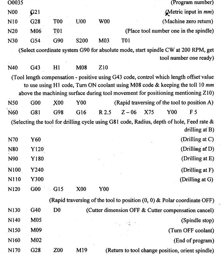
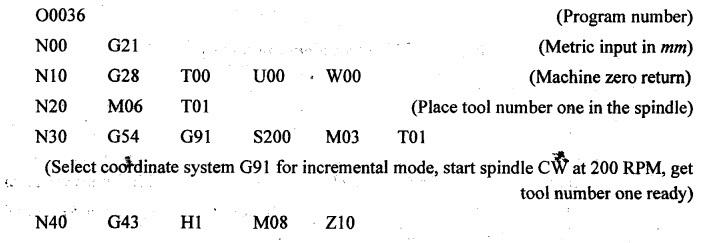
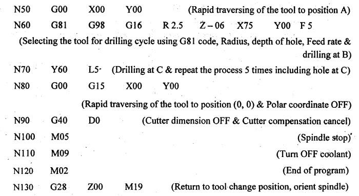
SOLVED ANNA UNIVERSITY PROBLEMS ON PART PROGRAMING AU Problem 5.1 Explain the part program segment given below. Draw the trajectory of table motion that this program seeks to create. N0010G90; N0011G01X1Y2; N0011G01X2Y2; N0013G91; N0014G01X1; N0015G92X2 Y2; N0016G01X1Y1 • N0010-N0016 refer step numbers • G 90 refers absolute programming • G01 refers linear interpolation (linear movement of tool), • X1 refers the tool movement by 1 unit in horizontal direction towards right • X2 refers the tool movement by 2 units in horizontal direction towards right • Y1 refers the tool movement by 1 unit in vertical direction towards up. • Y2 refers the tool movement by 2 units in vertical direction towards up. • G91 refers incremental dimensioning mode • G92 refers tool position register or setting new reference point. The directions of both X and Y are shown in Figure 5.40. Note:- In absolute mode, the movement is calculated and used to feed as data from fixed reference point. In incremental mode, the movement is calculated and used to feed as data between successive points. Drawing of the trajectory of table motion that the above program seeks to create as shown in Figure 5.41. The detailed steps are followed as given below: AU Problem 5.2 Figure 5.42 shows the finished size of a round bar. The original diameter of the bar was 28 mm. Make a part program for facing, parting and reduction of diameter. Take feed = 200 mm/min, spindle speed = 640 rpm and depth of cut = 2 mm pér cut. Solution: The part program is prepared for the tool position of A-B-C-D-E-F-G-H to manufacture the given component. Same sign conventions and codes as mentioned in Problem 5.1 are followed to prepare the part program. Programming in incremental mode: Programming in absolute mode: [Hint: In incremental mode, the distance is measured between successive points. But in absolute mode, the distance is measured from fixed reference point]. AU Problem 5.3 Write a manual part program to turn the component shown on a CNC Lathe from 75 mm bar stock. The following data may be assumed: (i) There will be two rough turnings and one finish turning. The first cut is with a depth of 3 mm for a length of 59 mm and the third with a depth of 1.5 mm for the full length of 60 mm. (ii) The shoulder of the workpiece is also machined during each cut. (iii) The spindle speed is 400 rpm and the feed rate is 0.5 mm/rev. Make a free-hand sketch showing relevant points of tool positions for each of the three turning operations and then write the manual part program. State also what each line of the program does. [May'12] Note: If the exact G-codes and M-codes are not known, the student can use his/her own code-numbers but the function of such codes must be clearly stated. Solution: First cut = 1 - 2 - 3 - 4 Second cut = - 2 - 5 - 6 - 7 Third cut = 5 - 8 - 9 - 10 [Hint:- Rather simply bringing the tool from point 1 to 2, 2 to 5 and 5 to 8, the condition of facing is assumed. Same sign conventions and codes as mentioned in Problem 5.1 are followed to prepare the part program.] Programming in incremental mode: Programming in absolute mode: AU Problem 5.4 A 110 mm long cylindrical rod of $75 mm is to be turned into a component as shown in Figure 5.46 using a CNC lathe. Write a CNC program for manufacturing this component. [May'12] Solution: The part program is prepared for the tool position of A-B-C-D-E-F-G-H-I-J-K to manufacture the given component. Same sign conventions and codes as mentioned in Problem 5.1 are followed to prepare the part program. Programming in incremental mode: (Select coordinate system, incremental mce, start spindle CW at 1500 RPM, get tool number one ready) It is assumed that chamfering is done for 3mm in both X and Y directions. AU Problem 5.5 Write a part program for that part shown in Figure 5.48. [Dec'10] Solution: The part program is prepared for the tool position of 0-B-A-C to manufacture the given component. Same sign conventions and codes as mentioned in Problem 5.1 are followed to prepare the part program. Programming in incremental mode: AU Problem 5.6 Write CNC part program for the component shown in Figure 5.49. Mention the assumptions made. [May'16] Solution: 1. First, the billet is reduced from 110 to 100 mm to avoid applying more depth of cut. So, the part program is prepared for reducing its diameter by turning for 150+3= 153 mm length (3 mm is given as allowance for parting-off). The tool positions are 1-2-3. 2. Then the program is continued for manufacturing the given component as per the given dimensions. The tool positions are A-B-C-D-E-F-G-H-I-J-K to manufacture the given component. Same sign conventions and codes as mentioned in Problem 5.1 are followed to prepare the part program. Programming in incremental mode: AU Problem 5.7 Write the necessary part program for the part shown in Figure 5.52. Solution: 1. First, the billet is reduced to 50 mm to avoid applying more depth of cut. So, the part program is prepared for reducing its diameter by turning for 500+3 = 503 mm length (3 mm is given as allowance for parting-off). The tool positions are 1-2-3. 2. Then the program is continued for manufacturing the given component as per the given dimensions. The tool positions are A-B-C-D-E-F-G-H-I-J-K to manufacture the given component. Same sign conventions are shown in Figure 5.53 to prepare the part program. Programming in incremental mode: AU Problem 5.8 Write a part program for drilling holes in the part shown in Figure 5.56. The plate thickness is 20 mm. [Dec'10] Solution: Program in absolute mode: AU Problem 5.9 A series of 5 mm hole (total number 6) are to be drilled in a circle of 150 mm diameter on a 6 mm glass sheet. Describe the method of manufacture to be used with a neat sketch of the setup. What are the process variables to be controlled giving their effect on the final hole quality and the production rate? [Apr'19] Solution: The part program is prepared for the tool position of A-B-C-D-E-F-G to drii the given. component. Same sign conventions as mentioned in Problem 5.1 are followed to prepare the part program. Program in absolute mode: Program in incremental mode: (Tool length compensation - positive using G43 code, control which length offset value to use using H1 code, Turn ON coolant using M08 code & keeping the toll 10 mm above the machining surface during tool movement for positioning mentioning Z10) Note:- In this case, additionally Macro variable K is used to refer the total number of holes minus one in machining process.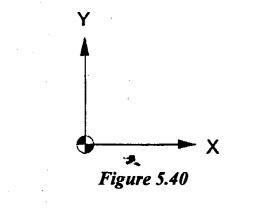


Manufacturing Technology: Unit V: Programming of CNC Machine Tools : Tag: : Programming of CNC Machine Tools - Manufacturing Technology - solved anna university problems on part programing
Related Topics
Related Subjects

Manufacturing Technology
ME3493 4th semester Mechanical Dept | 2021 Regulation | 4th Semester Mechanical Dept 2021 Regulation