Basic Electrical and Electronics Engineering: Unit I: Electrical Circuits
Single Phase AC Circuits
A current or voltage which alternates its direction and magnitude every time.
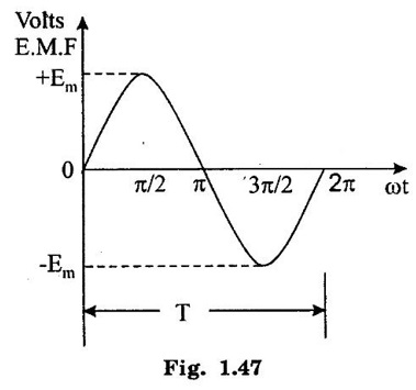
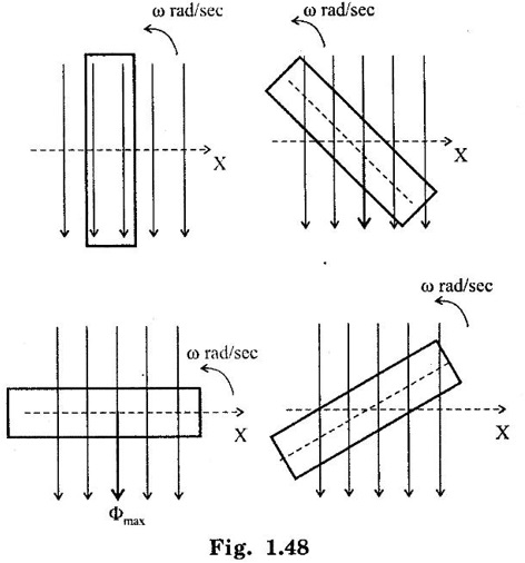
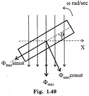
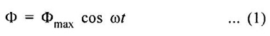
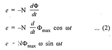
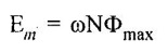
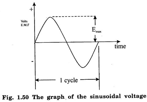
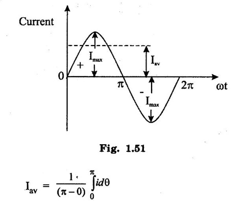
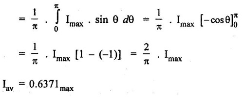
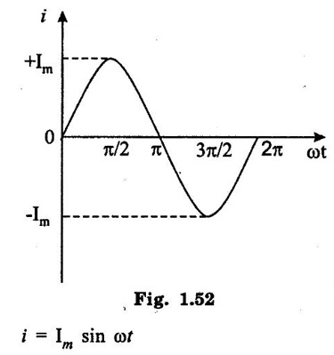
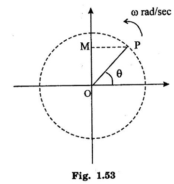
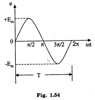
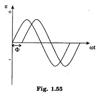
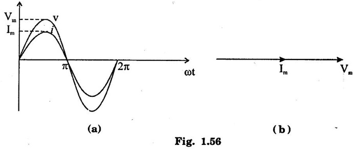
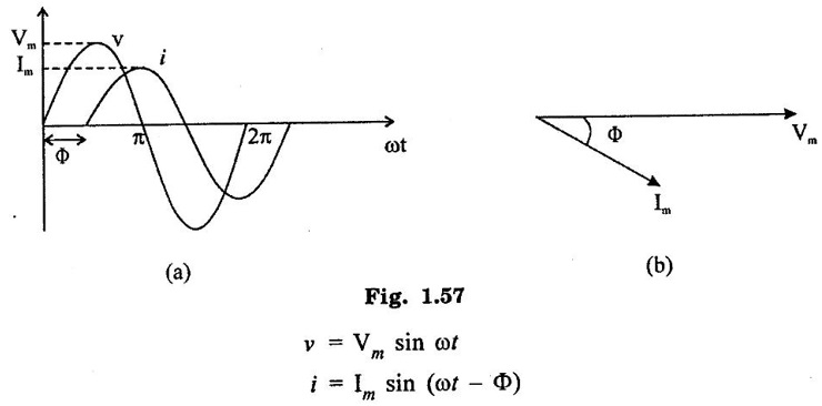
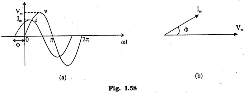
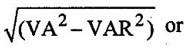
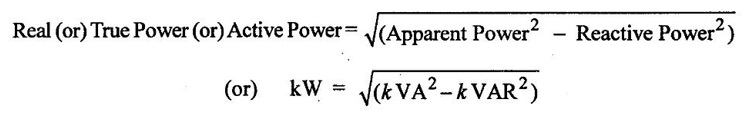
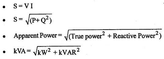
SINGLE PHASE AC CIRCUITS A current or voltage which alternates its direction and magnitude every time. Advantages of AC system over DC system 1. AC voltages can be efficiently stepped up/down using transformer. 2. AC motors are cheaper and simpler in construction than DC motors. 3. Switchgear for AC system is simpler than DC system. 4. More voltage can be generated (upto 33000V) than DC (650 V only). Consider a rectangular of N turns placed in a uniform magnetic field as shown in the figure 1.48. The coil is rotating in the anticlockwise direction at an uniform angular velocity of o rad/sec. When the coil is in the vertical position, the flux linking the coil is zero because the plane of the coil is parallel to the direction of the magnetic field. Hence at this position, the emf induced in the coil is zero. When the coil moves by some angle in the anticlockwise direction, there is a rate of change of flux linking the coil and hence an emf is induced in the coil. When the coil reaches the horizontal position, the flux linking the coil is maximum, and hence the emf induced is also maximum. When the coil further moves in the anticlockwise direction, the emf induced is the coil reduces. Next when the coil comes to the vertical position, the emf induced becomes zero. After that the same cycle repeats and the emf is induced in the opposite direction. When the coil completes one complete revolution, one cycle of AC voltage is generated. The generation of sinusoidal AC voltage can also be explained using mathematical equations. Consider a rectangular coil of N turns placed in a uniform magnetic field in the position shown in the figure 1.49. The maximum flux linking the coil is in the downward direction as shown in the figure 1.49. This flux can be divided into two components, one component acting along the plane of the coil Φmax sin ωt and another component acting perpendicular to the plane of the coil Φmax cos ωt. The component of flux acting along the plane of the coil does not induce any flux in the coil. Only the component acting perpendicular to the plane of the coil, (i.e.,) Φmax cos ωt induces an emf in the coil. It is determied from the relation. where Φmax = Maximum flux which can link with the coil t = Time taken by the coil to move through an angle Φ from vertical position. Using Faraday's law to equation (1), in order to the determine the voltage equation As the value of e will be maximum when sin of ωt = 1. Now equation (2) can be written as, e = Em sin ωt Hence the emf induced in the coil is a sinusoidal emf. This will induce a sinusoidal current in the circuit given by i = Im sin ωt Modern alternators produce an e.m.f. which is for all practical purposes sinusodal (i.e., a sine curve), the equation between the e.m.f. and time being where e = Instantaneous voltage; Emax = Maximum voltage ; ωt = Angle through which the armature has turned from neutral. Taking the frequency as ƒ hertz (cycles per second), the value of ω will be 2πƒ, so that the equation reads e = Emax sin (2πf) t The graph of the voltage will be as shown in fig. 1.46. 1. Cycle: One complete set of positive and negative values of an alternating quantity is known as a cycle. A cycle may also sometimes be specified in terms of angular measure. In that case, one complete cycle is said to spread over 360° or 2π radians. 2. Amplitude: The maximum value, positive or negative, of an alternating quantity, is known as its amplitude. 3. Frequency (f): The number of cycles/second is called the frequency of the alternating quantity. Its unit is hertz (Hz). 4. Time period (T): The time taken by an alternating quantity to complete the cycle is called its time period. Time period is reciprocal of frequency. 5. Root mean square (R.M.S) value: The r.m.s. (or effective) value of an alternating current is given by that steady (D.C) current which when flowing through a given circuit for a given time produces the same heat as produced by the alternating current when flowing through the same circuit for the same time. R.M.S. value is the value which is taken for power purposes of any description. This value is obtained by finding the square root of the mean value of the squared ordinates for a cycle or half cycle. (fig. 1:50). The equation of sinusoidal alternating current is given as : i = Imax sin θ The mean of squares of the instantaneous values of current over half cycle is Note: While solving problems, the values of given current and voltage should always be taken as the r.m.s. values, unless indicated otherwise. 6. Average or Mean value: The average value of an alternating current is expressed by that steady current which transfers across any circuit the same charge as is transferred by that alternating current during the same time. The mean value is only of use in connection with process where the results depend on the current only, irrespective of the voltage, such as electroplating or-battery charging. The value of instantaneous current is given by (Refer Fig. 1.51) i = Imax sin θ Refer Fig. 1.47. The value of instantaneous current is given by : i = Imax sin θ [θ = ωt] [Limits are taken from 0 to л, since only first half cycle is considered. For whole cycle, the average value of sine wave is zero]. Note: In case of unsymmetrical alternating current viz. half-wave rectified current the average value must always be taken over the whole cycle. Form factor: The ratio of r.m.s. (or effective) value to average value is the form factor (Kf) of the wave form. It has use in voltage generation and instrument correction factors. Peak factor: The ratio of maximum value to the rms value is called as peak factor (Kp) of the waveform. An alternating quantity can be represented using (i) Waveform (ii) Equations (iii) Phasor A sinusoidal alternating quantity can be represented by a rotating line called a Phasor. A phasor is a line of definite length rotating in anticlockwise direction at a constant angular velocity. The waveform and equation representation of an alternating current is as shown in figure 1.52 This sinusoidal quantity can also be represented using phasors. Draw a line OP of length equal to Im. This line OP rotates in the anticlokwise direction with a uniform angular velocity o rad/sec and follows the circular trajectory shown in figure. 1.53 At any instant, the projection of OP on the y-axis is given by OM = OP sin θ = Im sin ωt. Hence the line OP is the phasor representation of the sinusoidal current. Phase Phase is defined as the fractional part of time period or cycle through which the quantity has advanced from the selected zero position of reference. Phase of + Em is π/2 rad or T/4 sec Phase of - Em is 3π/2 rad or зT/4 sec. Phase Difference When two alternating quantities of the same frequency have different zero points, they are said to have a phase difference. The angle between the zero points is the angle of phase difference. in Phase Two waveforms are said to be in phase, when the phase difference between them is zero. That is the zero points of both the waveforms are same. The waveform, phasor and equation representation of two sinusoidal quantities which are in phase is as shown in figure 1.56. The figure 1.56(b) shows that the voltage and current are in phase. where, ν = Vm sin ωt i = Im sin ωt Lagging In the figure 1.57 shown, the zero point of the current waveform is after the zero point of the voltage waveform. Hence the current is lagging behind the voltage. The waveform, phasor and equation representation is as shown below. Leading In the figure 1.58 shown the zero point of the current waveform is before the zero point of the voltage waveform. Hence the current is leading the voltage. The waveform, phasor and equation representation is as shown below. ν = Vm sin ωt i = Im sin (ωt + Φ) Active Power is the actual power which is really transferred to the load such as transformer, induction motors, generators etc and dissipated in the circuit. Alternative words used for Real Power (Actual Power, True Power, Watt-full Power, Useful Power, Real Power, and Active Power) and denoted by (P) and measured in units of Watts (W) i.e. The unit of Real or Active power is Watt where 1W = 1V × 1 A. Active Power in DC Circuits: In DC Circuits, power supply to the DC load is simply the product of Voltage across the load and Current flowing through it i.e., P = V I because in DC Circuits, there is no concept of phase angle between current and voltage. In other words, there is no frequency (f) or Power factor in DC Circuits. Active Power in AC Circuits: But the situation in Sinusoidal or AC Circuits is more complex because of phase difference (θ) between Current and Voltage. Therefore average value of power (Real Power) is P = VI cos θ is in fact supplied to the load. In AC circuits, When circuit is pure resistive, then the same formula used for power as used in DC as P = V I. Active Power Formulas: ● P = V × I (In DC circuits) ● P = V × I × cos θ (in Single phase AC Circuits) ● P = ● P = 3 × Vph × Iph × cos θ ● Р = ● Р = Where: ● P = Power in Watts ● V = Voltages in Volts ● I = Current in Amperes ● Cos θ = Power Factor (Phase angle Difference) ● VL = Line Voltage ● IL = Line Current ● S = Apparent Power in VA (Volt Ampere) ● Q = Reactive Power in VAR (Volt Ampere Reactive) Also known as (Use-less Power, Watt less Power) The powers that continuously bounce back and forth between source and load is known as reactive Power (Q) Power merely absorbed and returned in load due to its reactive properties is referred to as reactive power. Reactive Power represent that the energy is first stored and then released in the form of magnetic field or electrostatic field in case of inductor and capacitor respectively. Reactive power is given by Q = V I Sinθ which can be positive (+ve) for inductive loads and negative (-ve) for capacitive load. The unit of Reactive Power is Volt-Ampere reactive i.e. VAR where 1 VAR = 1V × 1A. In more simple words, in Inductor or Capacitor, how much magnetic or electric field produced by 1A × 1V is known as the unit of Reactive Power. Reactive Power Formulas: ● Q = VI sin θ ● Reactive Power = ● VAR = ● kVAR = Where: θ = Phase angle The Product of voltage and current if and only if the phase angle differences between current and voltage are ignored. Total power in an AC circuit, both dissipated and absorbed/returned is referred to as apparent power. The combination of reactive power and true power is called apparent power. In an AC circuit, the product of the r.m.s voltage and the r.m.s current is called apparent power which is denoted by (S) and measured in units of Volt-amp (VA). It is the product of Voltage and Current without phase angle. The unit of Apparent power (S) VA i.e. 1VA = 1V × 1A. When the circuit is pure resistive, then apparent power is equal to real or true power, but in inductive or capacitive circuit, (when Reactances exist) then apparent power is greater than real or true power. Apparent Power Formulas:1. Introduction to Alternating current
2. Generation of sinusoidal AC voltage
3. Alternating Voltage and Current


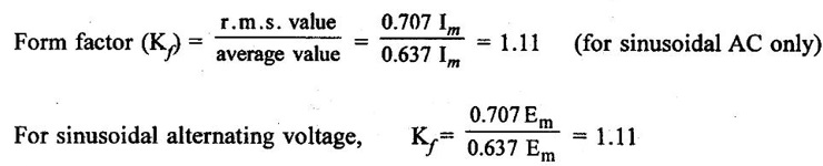
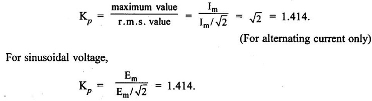
7. Form and Peak Factors
4. Phasor Representation
5. Active Power: (P)
 or (in Three Phase AC Circuits)
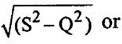
6. Reactive Power: (Q)
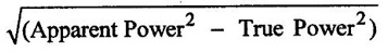
7. Apparent Power: (S)
Basic Electrical and Electronics Engineering: Unit I: Electrical Circuits : Tag: : - Single Phase AC Circuits
Related Topics
Related Subjects

Basic Electrical and Electronics Engineering
BE3251 2nd semester Mechanical Dept | 2021 Regulation | 2nd Semester Mechanical Dept 2021 Regulation

Basic Electrical and Electronics Engineering
BE3251 2nd Semester CSE Dept 2021 | Regulation | 2nd Semester CSE Dept 2021 Regulation