Fluid Mechanics and Machinery: Unit 1: Fluid Properties and Flow Characteristics
Simple manometer
Types, Construction Diagram, Working Principle
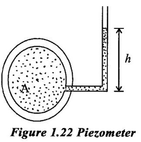
A simple manometer consists of a glass tube having one of its end connected to a pipe through which fluid flows where pressure is to be measured and remains open to atmosphere.
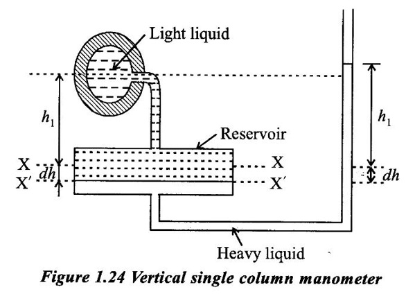
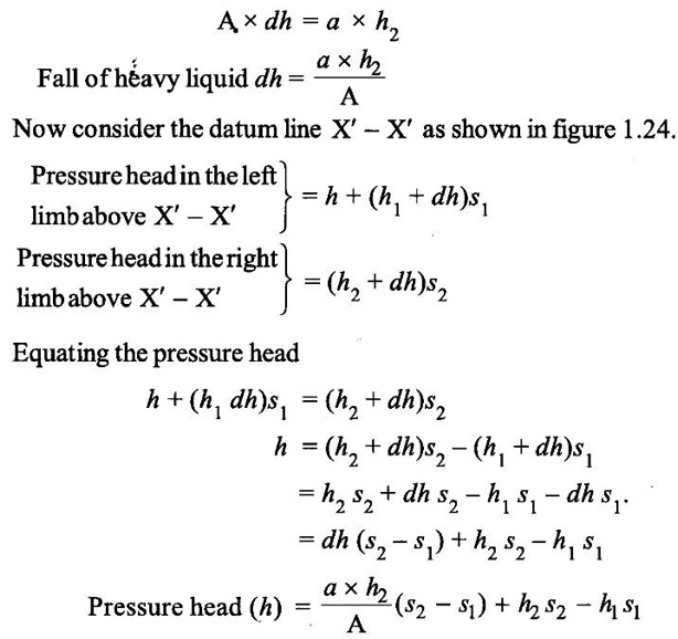
SIMPLE MANOMETER A simple manometer consists of a glass tube having one of its end connected to a pipe through which fluid flows where pressure is to be measured and remains open to atmosphere. Generally the following type of simple manometers are used. (i) Piezometer (ii) U-tube manometer (iii) Single column manometer In is the simplest form of manometer used for measured gauge pressure of flowing fluid. One end of this manometer is connected to the pipe where pressure in to be measured and other end is open to the atmosphere as shown in figure 1.22. This rise of liquid gives the pressure head at that pipe. It a pipe A, the height of liquid say water (h) in piezometer tube, then pressure at pipe A. Where P = w × h P= ρ × g × h ρ = density of liquid in kg/m3 g = acceleration due to gravity m/s2 h = height of liquid in the piezometer tube in m p = pressure in the pipe in N/m2. (i) Gas pressure cannot be measured. (ii) High pressure cannot be measured. It consist of glass tube bent in U-shape one end of which is connected to a pipe at which pressure is to be measured and other and remains open to the atmosphere as shown in figure 1.23. The U-tube contains generally mercury or any other liquid whose specific gravity is greater than the specific gravity of the liquid whose pressure is to be measured. s1 = specific gravity of pressure liquid s2 = specific gravity of manometric liquid h = pressure head in the pipe The pressure in the left limb and right limb of manometer above the datum line X- X are equal. (As the pressure is the same for the horizontal surfaces). (i) For positive pressure gauge The two limb pressures are equal to equating the above two equations. (ii) For Negative pressure gauge Equating above the two equations, = h + h1 s1 + h2 s2 = 0 Pressure head h = − (h1 s1 + h2 s2) Pressure P = W × h The U-tube manometer usually requires of fluid levels at two or more points. Since a change in pressure causes a rise liquid in one limb of the manometer and drop in the other. This difficulty in however overcomes by using single column manometer. In which a reservoir, having a large cross sectional area (about 100 times) as compared to the area of the tube is connected to left limb of the manometer as shown in figure 1.24. Due to large cross-sectional area of the reservoir if any variation in pressure the change in the liquid level in the reservoir will be so small that it may be neglected. The change in pressure indicated by the height of the liquid in the Right limb. A micrometer is used for measured very low pressure where accuracy is much important. This manometer is move sensitive so it is also called as sensitive manometer. The right limb of this manometer may be vertical or inclined. Thus there are two types of single column manometer as, (i) Vertical single column manometer (ii) Inclined single column manometer Figure 1.24 shows the vessizal single column manometer. Let X-X be the datum line in the reserving and in the left limb of manometer, where it is not connected to she pipe whose pressure is measured. The right limb of manometer tube is open so atmosphere and it containing heavy liquid (manometer liquid like as mercury). When the manometer left limb is connected to the light liquid containing pipe, (pressure measured liquid) due to high pressure of the pipe at A, the heavy liquid in the reservoir will be pushed, downward and will rise in the right limb. The change in datum line in the reservoir noted as X' - X'. Let, dh = fall of heavy liquid in reservoir h2 = rise of heavy liquid in right limb h1 = height of centre of pipe above X-X h = pressure head at pipe A A = cross-sectional area of the reservoir a = crossesectional area of the reservoir s1 = specific gravity of hight liquid in pipe s2 = specific gravity of heavy liquid in the reservoir. Fall of heavy liquid in reservoir will cause a rise of heavy liquid level in the right limb. When the area A is very large as compared to a, then the ratio a/A becomes very small and thus neglected, then the above equation becomes h = h2s2 – h1s1. θ = inclination of right limb with horizontal. h2 = vertical rise of heavy liquid in right limb from X-X = l × sin θ h = h2s2 = h1s1 (from previous type) h2 = l × sin θ ⸫ h = l × sin θs2 - h1s11. Piezometer
Limitations:
2. U-tube Manometer
 h1 = height of pressure measured liquid above datum line

3. Single Column Manometer (Micromanometer)
1. Vertical Single Column Manometer
2. Inclined Single Column Manometer
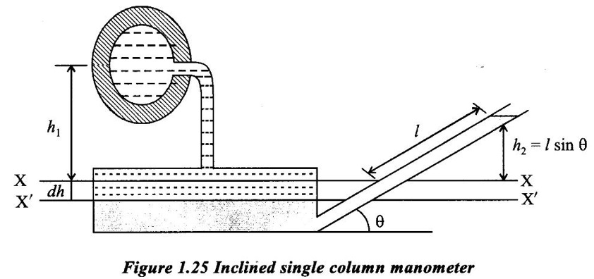 Figure 1.25 shows the inclined single column manometer with inclined tube. This manometer in move sensitive due to inclination the distance moved by the heavy liquid in the right limb will be more. Let L - length of heavy liquid moved in right limb from X-X.
Fluid Mechanics and Machinery: Unit 1: Fluid Properties and Flow Characteristics : Tag: : Types, Construction Diagram, Working Principle - Simple manometer
Related Topics
Related Subjects
Fluid Mechanics and Machinery
CE3391 3rd semester Mechanical Dept | 2021 Regulation | 3rd Semester Mechanical Dept 2021 Regulation