Basic Electrical and Electronics Engineering: Unit I: Electrical Circuits
RL Series Circuit
A circuit containing a pure resistance and pure inductance connected in series shown in figure 1.64(a).
RL SERIES CIRCUIT A circuit containing a pure resistance and pure inductance connected in series shown in figure 1.64(a). Let, V = rms value of applied voltage L = Inductance in henry I = Current flowing in RL series circuit (rms value) VR = Voltage drop across R VL = Voltage drop across L In a pure resistor circuit, V and I are in phase. In pure inductor circuit, the current said to be lagging by 90° with respect to VL. The applied voltage V is The quantity Z2 = R2 + XL2 where XL = Reactance Z = Impedance It is noted from the figure 1.64(c), the current I lags behind the applied voltage by angle ϕ.

 is called as impedance of the circuit. From the figure 1.64(c), phasor diagram, (OAB triangle)
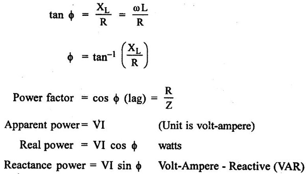
Basic Electrical and Electronics Engineering: Unit I: Electrical Circuits : Tag: : - RL Series Circuit
Related Topics
Related Subjects

Basic Electrical and Electronics Engineering
BE3251 2nd semester Mechanical Dept | 2021 Regulation | 2nd Semester Mechanical Dept 2021 Regulation

Basic Electrical and Electronics Engineering
BE3251 2nd Semester CSE Dept 2021 | Regulation | 2nd Semester CSE Dept 2021 Regulation