Fluid Mechanics and Machinery: Unit 4: Turbines
Reaction Turbine
Layout Diagram, Main parts, Components, Working Principle, Design Calculation
Reaction turbines consists of fixed and moving blades (or) vanes and runner utilizes both kinetic and pressure energy.
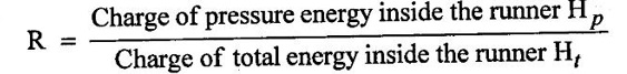
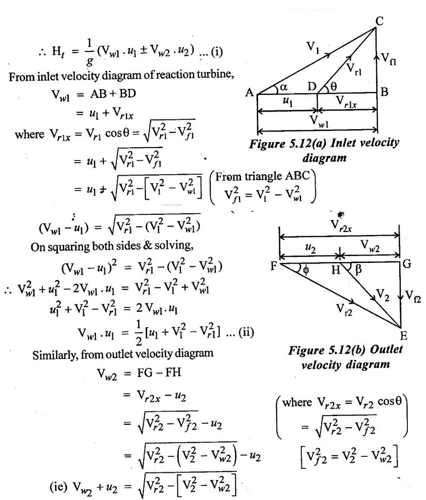
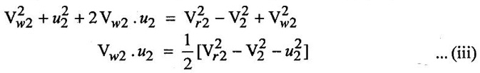
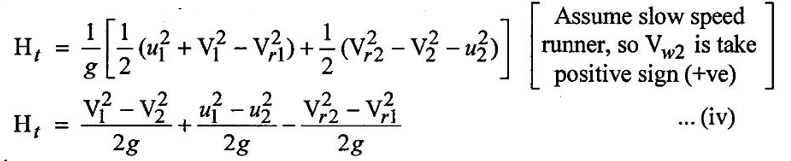
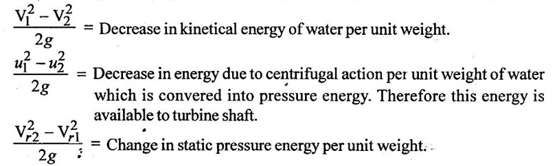
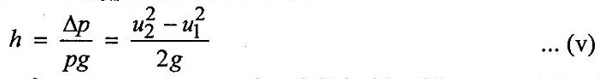
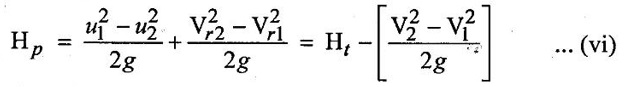
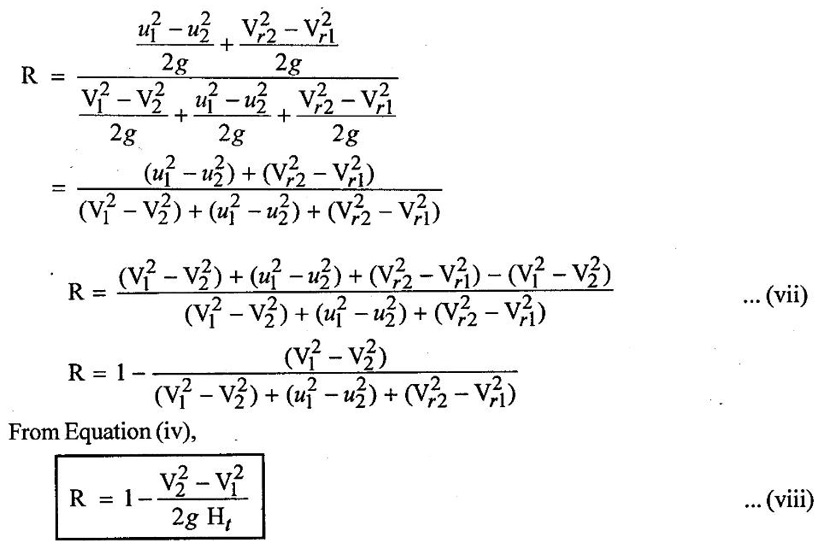
REACTION TURBINE Reaction turbines consists of fixed and moving blades (or) vanes and runner utilizes both kinetic and pressure energy. When water flows through the stationary parts of these turbines (fixed vanes (or) Guide Vanes) pressure energy of water is not completely converted into kinetic energy. Hence when the water flows through the moving blades of these turbines, there is a change in both pressure and absolute velocity of the water when it flows through the moving blades of the runner. The ruiner blades are always remian under pressure which in higher than the atmospheric pressure. This pressure varies when the water flows over the runner blades. The runner passage are always completely filled up with water in the reaction turbine. (i) Casing Casing and runner are always full of water. The water from the penstocks enters the casing which is of spiral (or) scroll shape in which area of cross-section of the casing goes on decreasing gradually. The casing completely, surrounds the runner of the turbine. The casing is spiral shape, so that the water enters the runner at constant velocity throughout the circumference of the runner. (ii) Stay Ring The speed ring (or) stay ring consists of the rings held together by series of fixed vanes called stay vanes. This ring directs water from the scroll casing to the guide vanes. It also transfers the loads (Caused by the water pressure, weight of the turbine and weight of generator) to the foundation. (iii) Guide Vanes (or) blades The guide vanes are fitted between two rings in the form of a wheel known as guide wheel. The guide vanes guide the water to enter tangentially to the runner blades (or) moving blades. Each guide vane is pivoted and it can be rotated about its pivot by a system of lever and links. After the rotation of guide vanes there will be a change in width of the water passage between them. Thus water flowing into the runner is varied accordingly to the requirement. (iv) Runner Runner is the most important circular rotary part of a water turbine. It consists of a series of curved blades (or) vanes which are fixed on its periphery in such a manner that the water enters radially into runner and exit axially without shock. The driving force on the runner is both due to impulse (Change in kinetic energy) and reaction (change in pressure energy). (v) Draft tube The water pressure at exit of the runner in reaction turbine is generally less than the atmospheric pressure, so the water at exit cannot be directly discharged to the tail race. A tube (or) pipe of gradually increasing the area is used for discharging water from the exit of the turbine to the tail race. This tube is called draft tube. Thus there is an increasing pressure with respect to the decreasing velocity. The water from the penstock enters the stationary guiding wheel. The guiding wheel consists of guide vanes which direct the water to enter the runner which consists of moving vanes. The water flows over the moving vanes in the inward radial direction and is discharged at the inner diameter of the runner. The runner is rotated due to the driving force while water flows over the runner vanes. So the runner converts hydraulic energy into mechanical energy. Finally this mechanical energy is converted into electrical energy through electric generator. Degree of reaction (R) of a runner is defined as the ratio of change of pressure energy inside the runner to the change of total energy inside the runner. Accordingly. But, change of total energy of inside the runner is equal to workdone per weight of water which is given by, On squaring both sides & solving the above equation we get, On substituting the values from equations (ii) & (iii) in equation (i), Change in total energy in runner Various changes in energy in the above expression represent the following ⸫ Change in pressure energy is caused due to centrifugal action, Hence, the change of pressure energy per unit weight inside of the runner is due to centrifugal action and due to change in static pressure energy. Change in pressure energy inside the runner per unit weight, represents last two terms, On substituting the value of Hp from equation (vi) & value of Ht from equation (iv) in degree of reaction (R).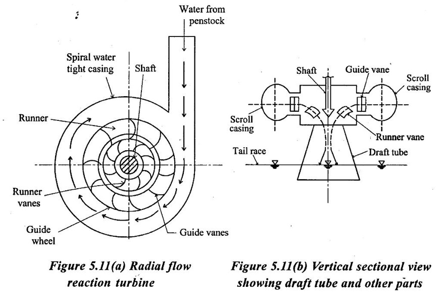
Main parts of Reaction turbine
Working Principle
1. Degree of Reaction (R)
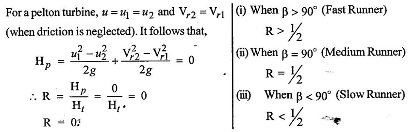
2. Degree of Reaction of Pelton wheel.
Fluid Mechanics and Machinery: Unit 4: Turbines : Tag: : Layout Diagram, Main parts, Components, Working Principle, Design Calculation - Reaction Turbine
Related Topics
Related Subjects
Fluid Mechanics and Machinery
CE3391 3rd semester Mechanical Dept | 2021 Regulation | 3rd Semester Mechanical Dept 2021 Regulation