Basic Electrical and Electronics Engineering: Unit I: Electrical Circuits
RC Series Circuit
A circuit containing a pure resistance and a pure capacitance connected in series as shown in figure 1.65.
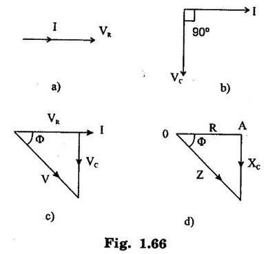
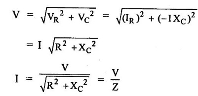
RC SERIES CIRCUIT A circuit containing a pure resistance and a pure capacitance connected in series as shown in figure 1.65. Figure 1.66(a) shows that in pure resistance circuit, V and I are in phase. In pure capacitor circuit (Fig. 1.66(b)), the current said to be leading by 90° with respect to VC. By combining these two vector diagrams of pure resistance and pure capacitance, we can obtain phasor diagram for RC series circuit as shown in figure 1.66 (c). Here VR = IR = drop across R VC = I XC = drop across capacitor. As capacitance reactance (XC) is taken as negative, VC is shown along negative direction of y-axis as shown in voltage triangle. In the figure 1.66(c), it is noted that I leads V by angle ϕ such that Apparent power = S = VI Real power = VI cos ϕ Reactive power Q = VI sin ϕ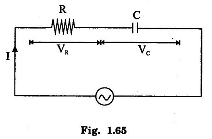

Basic Electrical and Electronics Engineering: Unit I: Electrical Circuits : Tag: : - RC Series Circuit
Related Topics
Related Subjects

Basic Electrical and Electronics Engineering
BE3251 2nd semester Mechanical Dept | 2021 Regulation | 2nd Semester Mechanical Dept 2021 Regulation

Basic Electrical and Electronics Engineering
BE3251 2nd Semester CSE Dept 2021 | Regulation | 2nd Semester CSE Dept 2021 Regulation