Manufacturing Technology: Unit V: Programming of CNC Machine Tools
programming of cnc machine tools
Programming of CNC Machine Tools - Manufacturing Technology
Commercial CNC system is capable simultaneously controlling two, two and a half, three, four and five degrees of freedom, or axes.
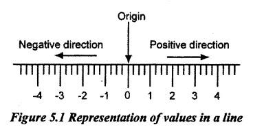
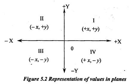
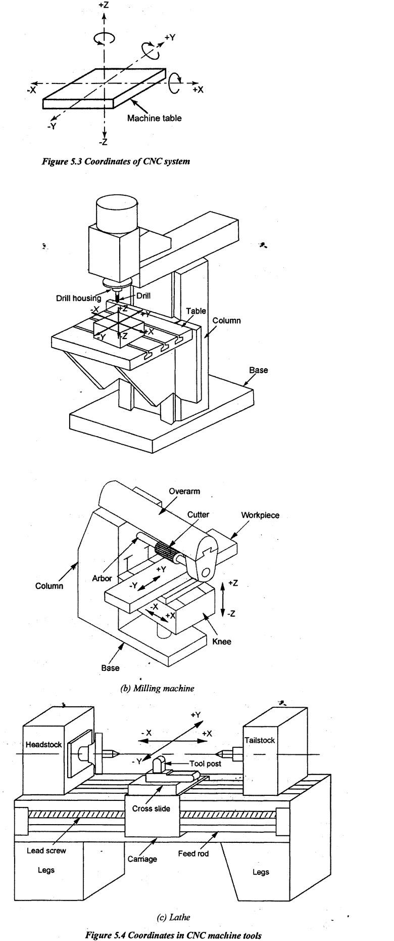
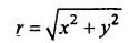
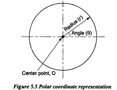
Unit - 5 PROGRAMMING OF CNC MACHINE TOOLS Coordinates, axis and motion, Absolute vs Incremental, Interpolators, Polar coordinates, Program planning, G and M codes, Manual part programming for CNC machining centers and Turning centers - Fixed cycles, Loops and subroutines, Setting up a CNC machine for machining. Commercial CNC system is capable simultaneously controlling two, two and a half, three, four and five degrees of freedom, or axes. CNC systems which control three linear translations or three linear translations and one rotation of the worktable are the most common. There are four types of coordinate systems followed in geometric constructions in mathematics. The same principles are replicated in setting coordinate systems for part programming in CNC machines, but only Cartesian and polar coordinate systems are familiar in CNC machines. So, it is better to discuss about the following systems. (i) Cartesian coordinate system (ii) Polar coordinate system (iii) Cylindrical coordinate system (iv) Spherical Coordinate system. 1. Cartesian Coordinate System Almost all CNC machine uses a Cartesian coordinate system based on an X, Y, and Z- axis due to the following reason that as proper manufacturing concepts in obtaining the degrees of freedom for the linear and transverse movements, each free body has six degrees of freedom. Among these degrees of freedom, three positive or negative translations are along X, Y and Z-axes and three rotations clockwise or counter-clockwise about these axes as shown in Figure 5.3. This coordinate system allows a machine to move in a specific direction along a specific plane. One point on the line is designated as the origin. Any numbers to the left of the origin are considered as negative values while numbers to the right are considered as positive values. When two axes are connected, they form a Plane. For example, when X and Y axes meet, an XY plane is arrived. These planes are divided into four quadrants, numbered I-IV, with their own positive and negative values. The easy way to understand the Cartesian coordinate system in relation to your CNC machine is using the Right-Hand Rule. To see axes lines clearly, place your hand out palm up with your thumb and index finger pointed outwards and your middle finger pointed upwards. Place your hand in front of your CNC machine. Thumb indicates X-axis, index finger indicates Y-axis and Middle finger indicates Z-axis. In CNC machine tools, each axis of motion is equipped with a separate driving device. which replaces the hand wheel of the conventional machine. The driving device may be a DC motor, a hydraulic actuator or a stepping motor. The type of motor selection mainly depends on power requirements of the machine. In the axis of the motion, an axis refers to a plane in which the cutting tool moves relative to the workpiece. This movement is achieved by the motion of the machine tool slides. The main three axes of motion will be referred as X, Y and Z-axes. Here, Z-axis is perpendicular to both X and Y as shown in Figure 5.4(a). The positive motion in Z direction moves the cutting tool away from the workpiece. The location of the origin X = Y = Z = 0 may be fixed or adjustable. In drilling and milling machines, X and Y-axes are horizontal as shown in Figure 5.4(a) and (b). A positive motion command in the drill moves X-axis from left to right, Y-axis moving forward and Z- axis towards the top. In milling machines, the directions are reversed. In lathes as shown in Figure 5.4(c), two axes are only required to command the motions of the tool. Since the spindle is horizontal, X-axis is horizontal. The cross axis is denoted by Y. A positive position command moves X-axis from left to right and Y-axis moving forward in order to create a right-hand coordinate system. In addition to the primary slide motions, if the secondary linear slide notions exist, they may be designated U, V and W. Rotary motions around the axes parallel to X, Y and Z are designated as a, b and c respectively. The purpose of the coordinate system is to provide a means of locating the tool in relation to the workpiece. Depending on NC machines, the part programmer may have several different options available for specifying this location. 2. Polar coordinates in CNC Machines Polar coordinate system represents the use of an angle and a distance relative to the origin. Depending on the control, both absolute part zero and current position origins are chosen for machining. For example, the radius of 8 cm with an angle of 30° is represented by X8 Y30 from origin in CNC part programing. To convert from Cartesian coordinate to Polar coordinate, Angle included with reference line, θ = tan-1 (y / x) Similarly, to convert from Polar coordinate o Cartesian coordinate: x = r cos θ y = r sin θ Polar coordinates are very common on non-Fanuc controls due to the availability of standard feature. Fanuc offers polar coordinates only as a special control option. Polar coordinate system is more effective for rotational axes than Cartesian coordinate-system. Mostly, commercial motion control cards do not provide sufficient support to the polar coordinate but it can be integrated into computer numeric control (CNC) controller based on motion control cards. In CNC machining, G16 is used to switch ON to the polar coordinate from Cartesian coordinate system and G15 is used to switch OFF to Cartesian coordinates. Drilling the bolt- circle in a plate mainly uses the polar coordinate system. For example, N... G9... G8... X... Y... R... Z... F... N... refers block number G9... & G8... refers G codes for the respective functions X... refers radius of the bolt center from origin Y... refers angle of bolt center from reference line R... refers radius of the bolt size Z... refers the depth of bolt hole F... refers the feed rate. An example of the program is discussed in manual part programing later.1. COORDINATES, AXIS AND MOTION OF CNC MACHINE TOOL
Manufacturing Technology: Unit V: Programming of CNC Machine Tools : Tag: : Programming of CNC Machine Tools - Manufacturing Technology - programming of cnc machine tools
Related Topics
Related Subjects

Manufacturing Technology
ME3493 4th semester Mechanical Dept | 2021 Regulation | 4th Semester Mechanical Dept 2021 Regulation