Manufacturing Technology: Unit V: Programming of CNC Machine Tools
part programs for turning, milling and drilling
Programming of CNC Machine Tools - Manufacturing Technology
For turning and facing processes, code G01 is used and code G00 is used for rapid traversing of the tool to the required position.
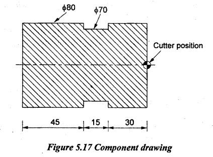
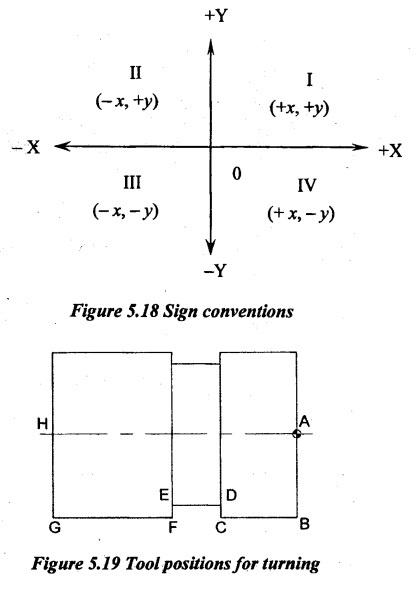
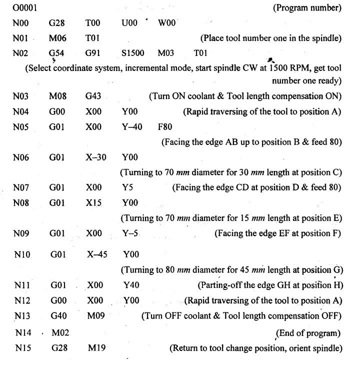
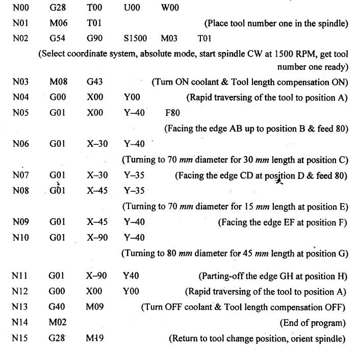
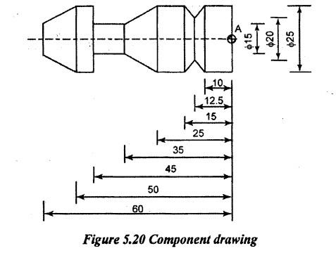
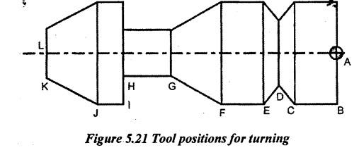
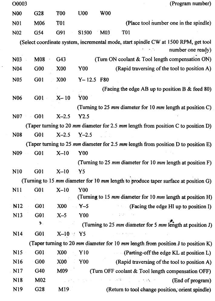
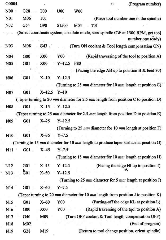
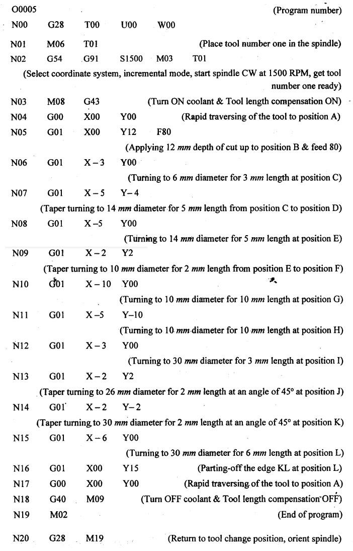
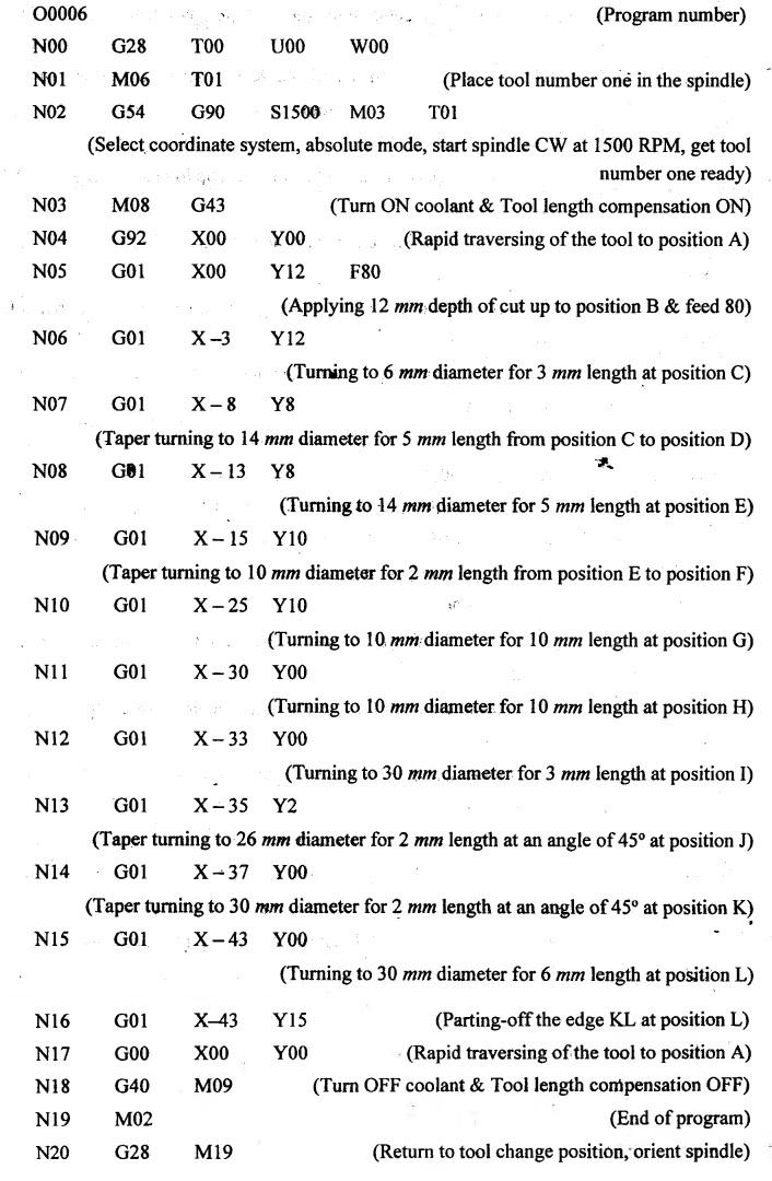
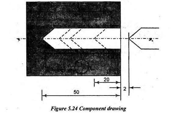
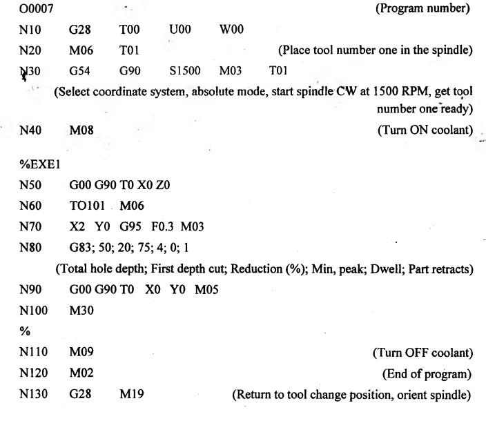
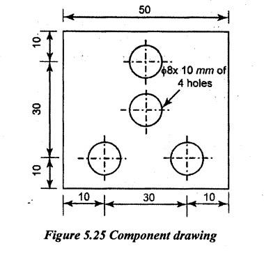
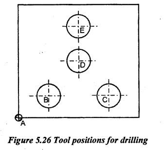
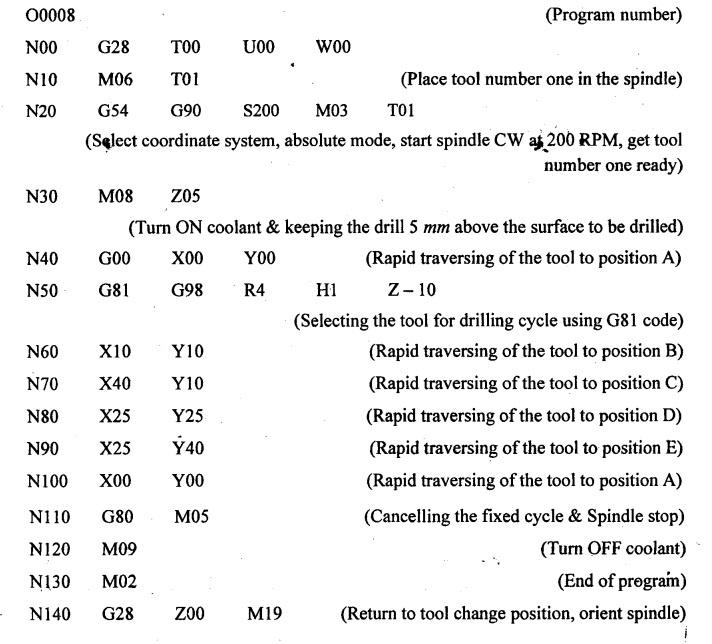
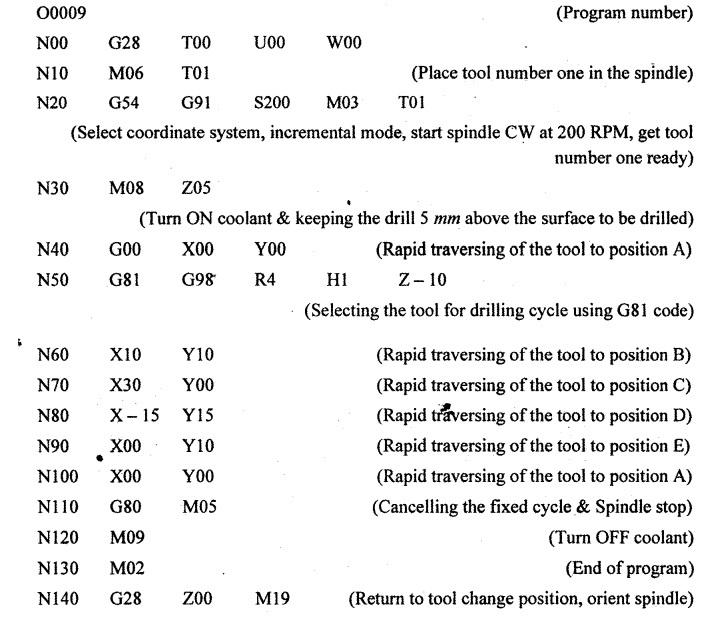
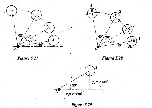
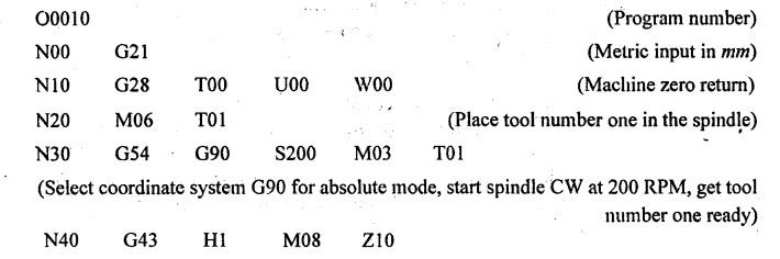
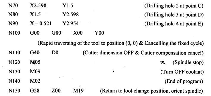
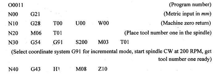
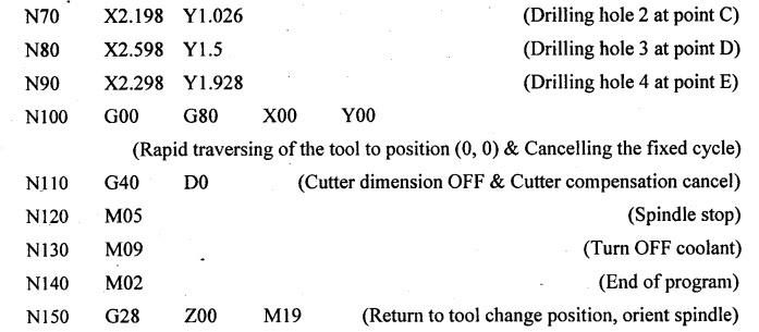
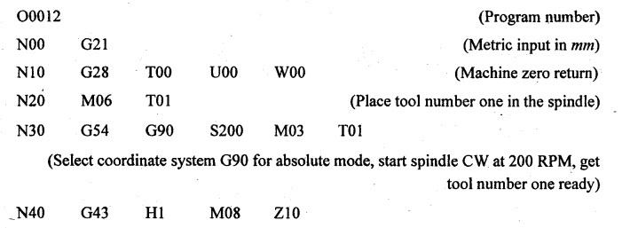
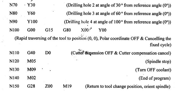
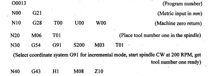
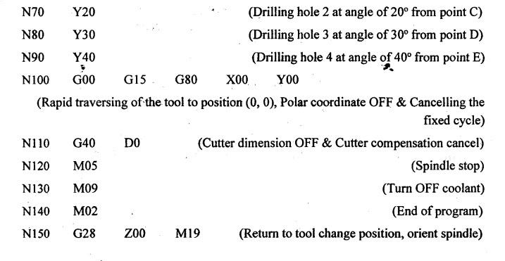
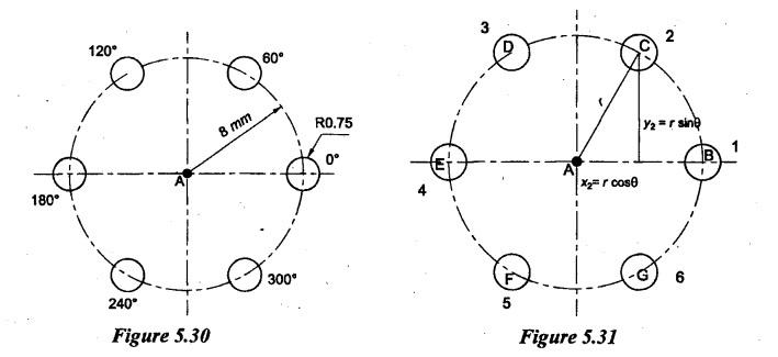
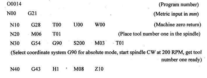
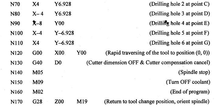
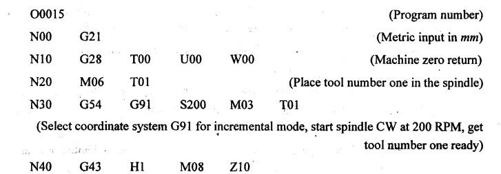
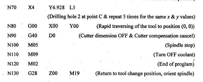
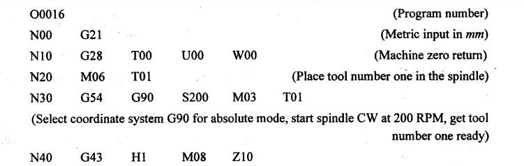
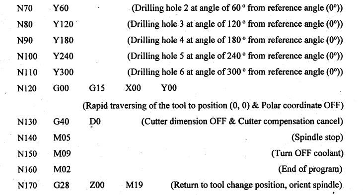
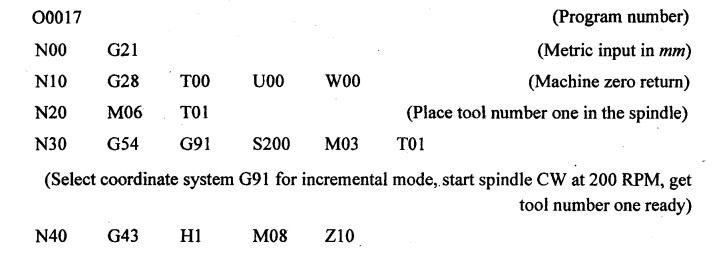
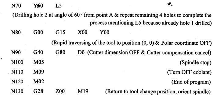
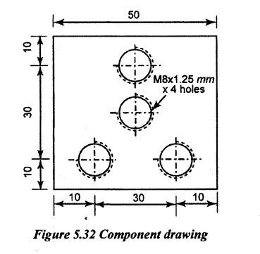
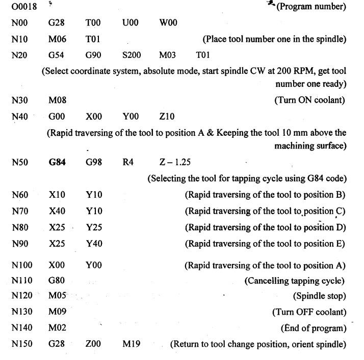
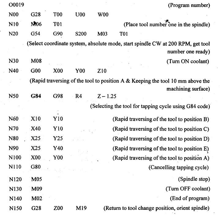
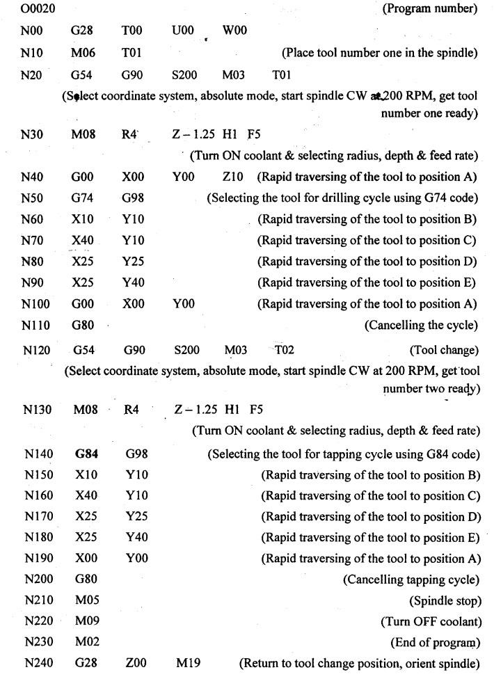
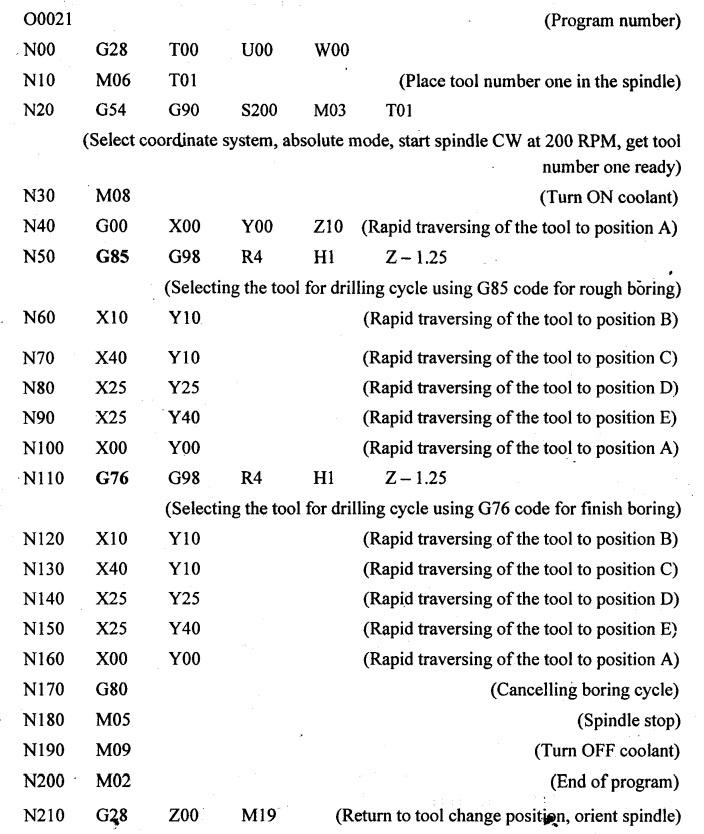
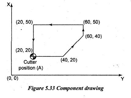
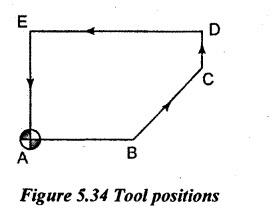
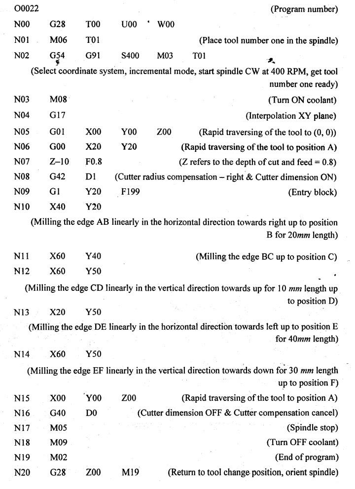
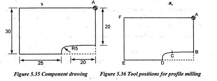
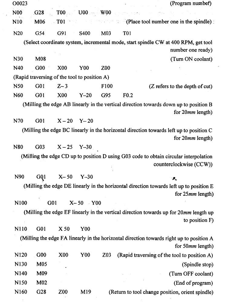
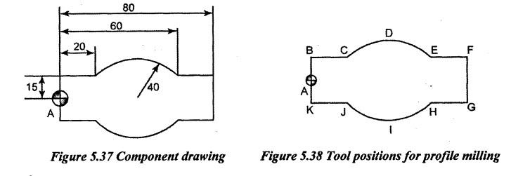
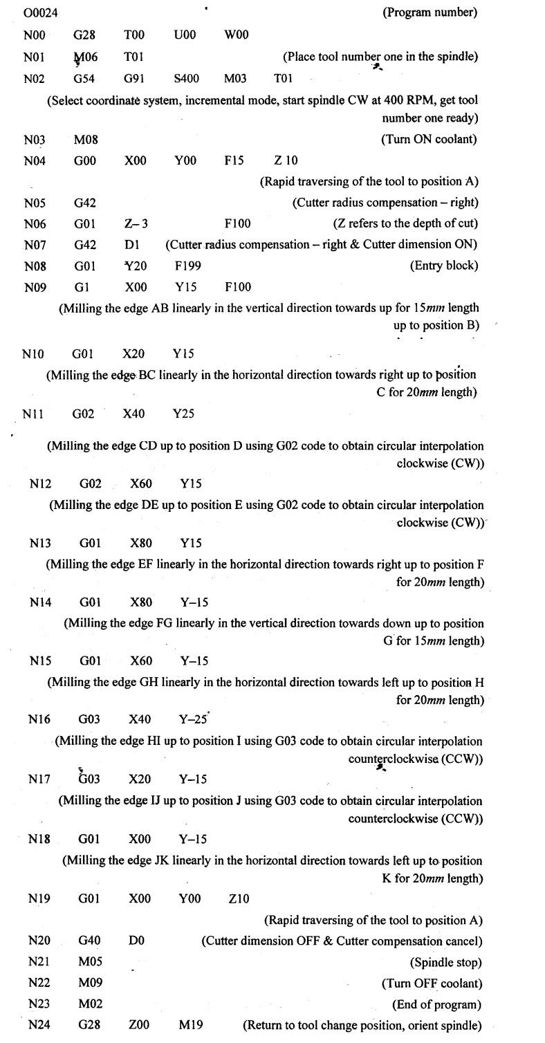
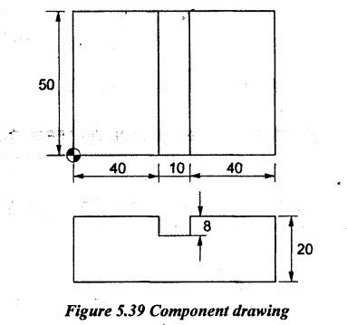
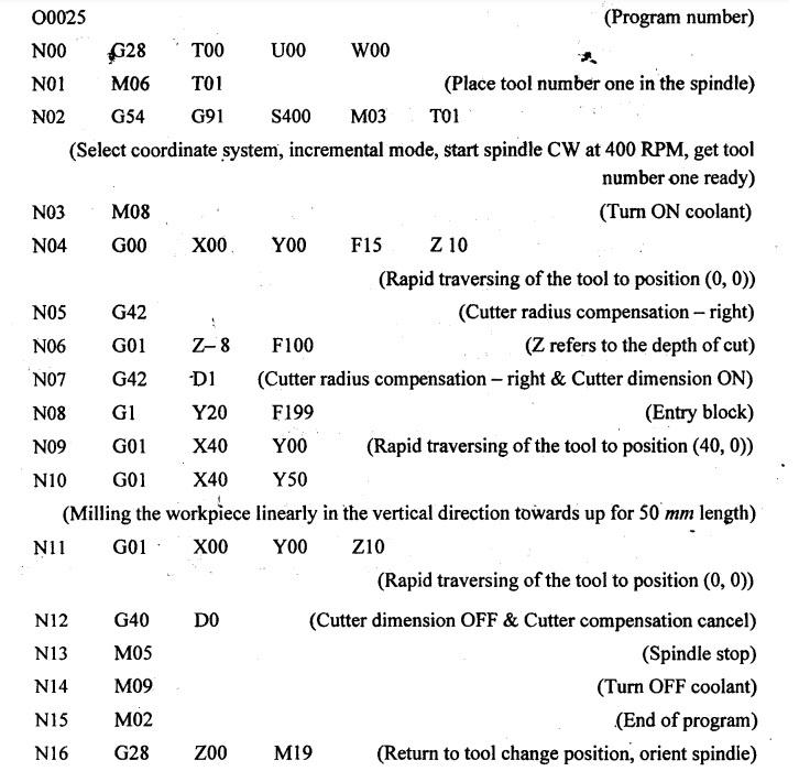
PART PROGRAMS FOR TURNING, MILLING AND DRILLING (All dimensions are in mm for all programs and Figures) Problem 5.1 Prepare a part program for manufacturing the given component for the given dimensions as shown in Figure 5.17. Solution: The part program is prepared for the tool position from A-B-C-D-E-F-G-H to perform the given component. For turning and facing processes, code G01 is used and code G00 is used for rapid traversing of the tool to the required position. The part program is prepared for the tool position of A-B-C-D-E-F-G-H to manufacture the given component. Programming in incremental mode: Programming in absolute mode: [Hint: In incremental mode, the distance is measured between successive points. But in absolute mode, the distance is measured from fixed reference point]. Problem 5.2 A 60 mm long cylindrical is to be turned into a component as shown in Figure 5.20 using a CNC lathe. Prepare a part program for manufacturing this component. Solution: The part program is prepared for the tool position of A-B-C-D-E-F-G-H-I-J-K-L to manufacture the given component. Same sign conventions and codes as mentioned in Problem 5.1 are followed to prepare the part program. Programming in incremental mode: Programming in absolute mode: [Hint: In incremental mode, the distance is measured between successive points. But in absolute mode, the distance is measured from fixed reference point]. Problem 5.3 A 43 mm long cylindrical is to be turned into a component as shown in Figure 5,22. using a CNC lathe. Prepare a part program for manufacturing this component. Assume that the right side edge of the workpiece is already machined. Solution: The part program is prepared for the tool position of A-B-C-D-E-F-G-H-I-J-K-L-M to manufacture the given component. Same sign conventions and codes as mentioned in Problem 5.1 are followed to prepare the part program. Program in incremental mode: Program in absolute mode: [Hint: In incremental mode, the distance is measured between successive points. But in absolute mode, the distance is measured from fixed reference point]. Problem 5.4 Prepare a part program for manufacturing the given component shown in Figure 5.24 in CNC drilling machine. Solution: Problem 5.5 Prepare a part program to drill the given component of 10 mm thick shown in Figure 5.25 in a CNC drilling machine. Solution: The part program is prepared for the tool position of A-B-C-D-E to drill the given component. Same sign conventions as mentioned in Problem 5.1 are followed to prepare the part program. Program in absolute mode: Program in incremental mode: Problem 5.6 Prepare the part programs by using both cartesian and polar coordinate systems for drilling 4 equispaced holes in 3 mm PCD of 0.5 mm radius for 1 mm depth from reference point at various angles in a given plate as per dimension shown in Figure 5.27 by drilling process in a CNC drilling machine. Solution: Case (i): Cartesian coordinate system (Absolute mode) To perform CNC drilling in cartesian coordinate, initially, radius of the pitch circle & subtended angle of center of the hole with reference point should be converted into x & y values. Example, for hole 1, x1 = r cos θ = 3 × cos 10° = 2.954 mm & y1 = r sin θ = 3 × sin 10° = 0.521 mm Similarly, coordinate distances are calculated such as For hole 2, x2 = r cos θ = 3 × cos 30° = 2.598 mm & y2 = r sin θ = 3 × sin 30° = 1.5 mm For hole 3, x3 r cos θ = 3 × cos 60° = 1.5 mm & y3 = r sin θ = 3 × sin 60° = 2.598 mm For hole 4, x4 = r cos θ = 3 × cos 100° = -0.521 mm & y4 = r sin θ = 3 × sin 100° = 2.954 mm Program in absolute mode: (Tool length compensation - positive using G43 code, control which length offset value to use using H1 code, Turn ON coolant using M08 code & keeping the toll 10 mm above the machining surface during tool movement for positioning mentioning Z10) (Selecting the tool for drilling cycle using G81 code, selecting G98 for Return to initial level in fixed cycle, hole radius of 0.5 mm (R0.5), hole depth of 1.0 mm (Z – 1.0), X coordinate distance for hole 1. Y coordinate distance for hole 1& feed rate for hole 1 at point B) Case (ii): Cartesian coordinate system (Incremental mode) Similar to absolute mode, again radius of the pitch circle & subtended angle of center of the hole with reference point should be converted into x & y values because angle between successive holes differs except hole 1. Example, for hole 1, x1 = r cos θ = 3 × cos 10° = 2.954 mm & y1 = r sin θ = 3 × sin 10° = 0.521 mm Similarly, coordinate distances are calculated such as For hole 2, x2 = r cos θ = 3 × cos 20° = 2.198 mm & y2 = r sin θ = 3 × sin 20° = 1.026 mm For hole 3, x3 r cos θ = 3 × cos 30° = 2.598 mm & y3 = r sin θ = 3 × sin 30° = 1.5 mm For hole 4, x4 = r cos θ = 3 × cos 40° = 2.298 mm & y4 = r sin θ = 3 × sin 40° = 1.928 mm Program in incremental mode: (Tool length compensation - positive using G43 code, control which length offset value to use using H1 code, Turn ON coolant using M08 code & keeping the toll 10 mm above the machining surface during tool movement for positioning mentioning Z10) (Selecting the tool for drilling cycle using G81 code, selecting G98 for Return to initial level in fixed cycle, hole radius of 0.5 mm (R0.5), hole depth of 1.0 mm (Z – 1.0), X coordinate distance for hole 1, Y coordinate distance for hole 1& feed rate for hole 1 at point B) Case (iii): Polar coordinate system (Absolute mode) To avoid complexity in calculating coordinate distances using sine and cosine rule. At the same time, error occurs after 3rd decimal (4th decimal ignored). So exact position of the hole is not possible in cartesian coordinate system. It is better to use polar coordinate system without these complexities. (Tool length compensation - positive using G43 code, control which length offset value to use using H1 code, Turn ON coolant using M08 code & keeping the toll 10 mm above the machining surface during tool movement for positioning mentioning Z10) (Selecting the tool for drilling cycle using G81 code, selecting G98 for Return to initial level in fixed cycle, selecting G16 for polar coordinate, hole radius of 0.5 mm (R0.5), hole depth of 1.0 mm (Z − 1.0), X3 & Y10 for hole 1 at point B) Case (iv): Polar coordinate system (Incremental mode) (Tool length compensation - positive using G43 code, control which length offset value to use using H1 code, Turn ON coolant using M08 code & keeping the toll 10 mm above the machining surface during tool movement for positioning mentioning Z10) (Selecting the tool for drilling cycle using G81 code, selecting G98 for Return to initial level in fixed cycle, selecting G16 for polar coordinate, hole radius of 0.5 mm (R0.5), hole depth of 1.0 mm (Z – 1.0), X3 & Y10 for hole 1 at point B) Problem 5.7 Prepare the part programs by using both cartesian and polar coordinate systems for drilling 6 equispaced holes and in equal angle to each other for 1.5 mm depth from reference point of 0.75 mm radius and 16 mm PCD in a given plate as per dimension shown in Figure 5.30 by drilling process in a CNC drilling machine. Pitch circle diameter = 16 mm ⸫ Pitch circle radius = 16/2 = 8 mm Solution: Case (i): Cartesian coordinate system (Absolute mode) To perform CNC drilling in cartesian coordinate, initially, radius of the pitch circle & subtended angle of center of the hole with reference point should be converted into x & y values. Example, for hole 1, x1 = r cos θ = 8 × cos 0° = 8 mm & y1 = r sin θ = 8 × sin 0° = 00 mm Similarly, coordinate distances are calculated such as For hole 2, x2 = r cos θ = 8 × cos 60° = 4 mm & y2 = r sin θ = 8 × sin 60° = 6.928 mm For hole 3, x3 r cos θ = 8 × cos 120° = -4 mm & y3 = r sin θ = 8 × sin 120° = 6.928 mm For hole 4, x4 = r cos θ = 8 × cos 180° = -8 mm & y4 = r sin θ = 8 × sin 180° = 00 mm For hole 5, x5 = r cos θ = 8 × cos 240° = -4 mm & y5 = r sin θ = 8 × sin 240° = -6.928 mm For hole 6, x6 = r cos θ = 8 × cos 300° = 4 mm & y6 = r sin θ = 8 × sin 300° = -6.928 mm Program in absolute mode: (Tool length compensation - positive using G43 code, control which length offset value to use using H1 code, Turn ON coolant using M08 code & keeping the toll 10 mm above the machining surface during tool movement for positioning mentioning Z10) (Selecting the tool for drilling cycle using G81 code, selecting G98 for Return to initial level in fixed cycle, hole radius of 0.75 mm (R0.75), hole depth of 1.5 mm (Z- 1.5), X8 & Y00 for hole 1 at point B) Case (ii): Cartesian coordinate system (Incremental mode) To perform CNC drilling in cartesian coordinate, initially, radius of the pitch circle & subtended angle of center of the hole with reference point should be converted into x & y values. Example, for hole 1, x1 = r cos θ = 8 × cos 0° = 8 mm & y1 = r sin θ = 8 × sin 0° = 00 mm Similarly, coordinate distances are calculated such as For hole 2, x2 = r cos θ = 8 × cos 60° = 4 mm & y2 = r sin θ = 8 × sin 60° = 6.928 mm It is well known that x and y values for holes 3, 4, 5 & 6 are same as hole 2 because subtended angle between successive holes is constant. So, no further calculations are required. Program in incremental mode: (Tool length compensation - positive using G43 code, control which length offset value to use using H1 code, Turn ON coolant using M08 code & keeping the toll 10 mm above the machining surface during tool movement for positioning mentioning Z10) (Selecting the tool for drilling cycle using G81 code, selecting G98 for Return to initial level in fixed cycle, hole radius of 0.75 mm (R0.75), hole depth of 1.5 mm (Z-1.5), X8 & Y00 for hole 1 at point B) Case (iii): Polar coordinate system (Absolute mode). (Tool length compensation - positive using G43 code, control which length offset value to use using H1 code, Turn ON coolant using M08 code & keeping the toll 10 mm above the machining surface during tool movement for positioning mentioning Z10) (Selecting the tool for drilling cycle using G81 code, selecting G98 for Return to initial level in fixed cycle, selecting G16 for polar coordinate, hole radius of 0.75 mm (R0,75), hole depth of 1.5 mm (Z – 1.5), pitch circle radius 8 mm mentioning X3 & Y00 is for angle of the hole to be placed from point A) Case (iv): Polar coordinate system (Incremental mode) (Tool length compensation - positive using G43 code, control which length offset value to use using H1 code, Turn ON coolant using M08 code & keeping the toll 10 mm above the machining surface during tool movement for positioning mentioning Z10) (Selecting the tool for drilling cycle using G81 code, selecting G98 for Return to initial level in fixed cycle, selecting G16 for polar coordinate, hole radius of 0.75 mm (R0.75), hole depth of 1.5 mm (Z – 1.5), pitch circle radius 8 mm mentioning X3 & Y00 is for angle of the hole to be placed from point A) Problem 5.8 Prepare a part program for manufacturing right hand internal threads in above mentioned component shown in Figure 5.32 in a CNC machine. Solution: For M8 tap, code G84 is selected. So, above written part program for drilling is used just by replacing G74 code by G84 because G84 is used for tapping process with right hand threads) Program in absolute mode: [Hint:- 1. For producing left hand internal threads by tapping process, above written Part program is same but the code G84 should be replaced by G84 because G74 is used to produce right hand internal threads only. 2. To manufacture the internal threads by tapping can also be performed in two stages such as drilling holes on the given workpiece and tapping the drilled holes. For such case, the part programs of drilling and tapping processes are combined to make to a single program.) Program in incremental mode: Problem 5.9 Prepare a part program for manufacturing right hand internal threads in a given plate by drilling process followed by tapping process in above mentioned component shown in Figure 5.32 in a CNC machine. Solution: Part program for combined drilling and Tapping: Problem 5.10 Prepare a part program for enlarging the drilled holes 48 mm to $10 mm by boring process for above mentioned component shown in Figure 5.32 in a CNC machine. Solution: For boring, code G85 or G86 is used for rough boring and G76 is used for finish boring. Rough boring is carried out with ϕ 39 mm boring bar and finish boring is carried out with ϕ 40 mm boring bar. Part program: [Hint:- Reaming can also be performed by using the similar part program of finish boring.] Problem 5.11 Prepare a part program for manufacturing the given component shown in Figure 5.33 profile milling process in a CNC milling machine by considering cutter compensation. Solution: The part program is prepared in incremental mode for the tool position of A-B-C-D-E to mill the given component. Same sign conventions as mentioned in Problem 5.1 are followed to prepare the part program. Part program in incremental mode: Problem 5.12 Prepare a part program for manufacturing the given component shown in Figure 5.35 by profile milling using a CNC milling machine. Solution: The part program is prepared in incremental mode for the tool position of A-B-C-D-E-F to mill the given component. Same sign conventions as mentioned in Problem 5.1 are followed to prepare the part program. Part program in incremental mode: Problem 5.13 Prepare a part program for manufacturing the given component shown in Figure 5.37 by profile milling process in a CNC milling machine by considering cutter compensation. Solution: The part program is prepared in incremental mode for the tool position of A-B-C-D-E-F- G-H-I-J-K to mill the given component. Same sign conventions as mentioned in Problem 5.1 are followed to prepare the part program. Part program in incremental mode: Problem 5.14 Prepare a part program for milling a slot for the width of 10 mm on the given component Figure 5.39 by slot milling process in a CNC milling machine. Solution: Part program in incremental mode:1. Part Programming for CNC Turning Centers

2. Part Programming for CNC Drilling Centers
3. Part Programming for CNC Drilling using Polar Coordinate System


4. Part Programming for CNC Tapping Centers
5. Part Programming for CNC Boring Centers
6. Part Programming for CNC Milling Centers
Manufacturing Technology: Unit V: Programming of CNC Machine Tools : Tag: : Programming of CNC Machine Tools - Manufacturing Technology - part programs for turning, milling and drilling
Related Topics
Related Subjects

Manufacturing Technology
ME3493 4th semester Mechanical Dept | 2021 Regulation | 4th Semester Mechanical Dept 2021 Regulation