Basic Electrical and Electronics Engineering: Unit I: Electrical Circuits
Parallel RLC Circuit
with Solved Example Problems
Therefore, the equivalent complex admittance for a parallel circuit may be obtained by addition of all complex admittances in parallel and reciprocal of equivalent complex admittance is equivalent complex impedance.
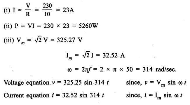
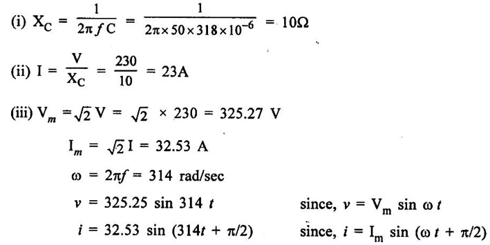
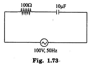
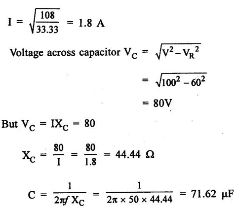
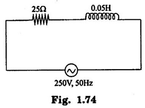
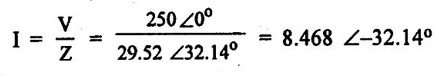
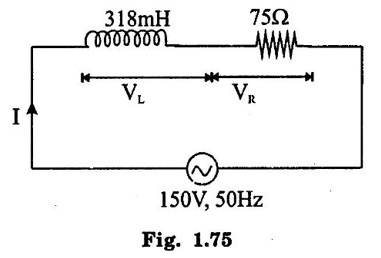
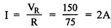
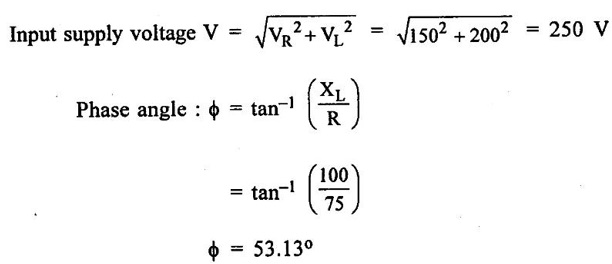
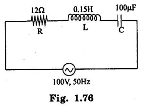
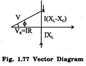
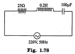
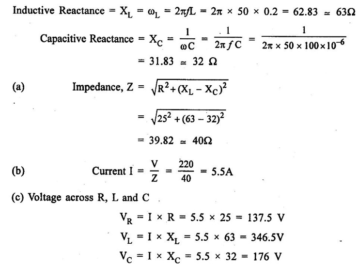
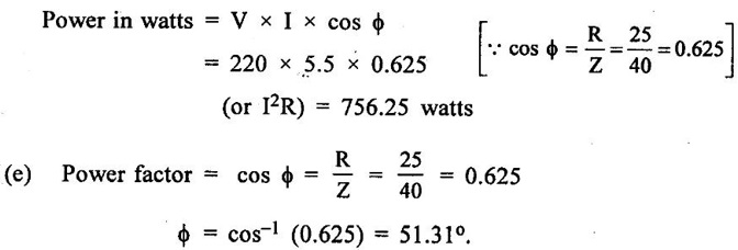
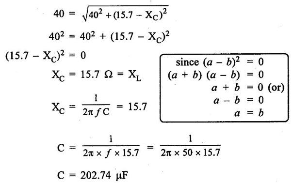
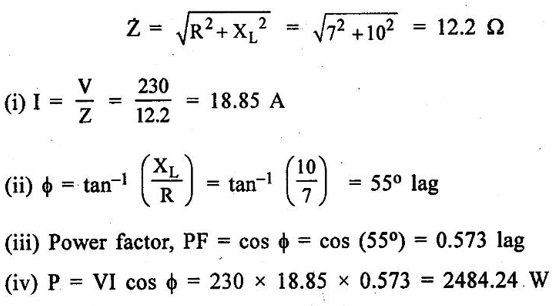
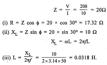
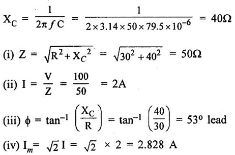
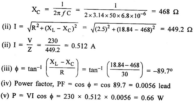
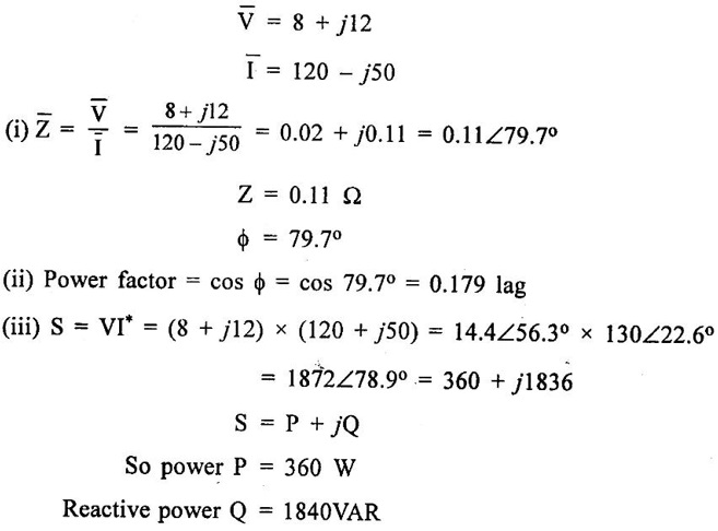
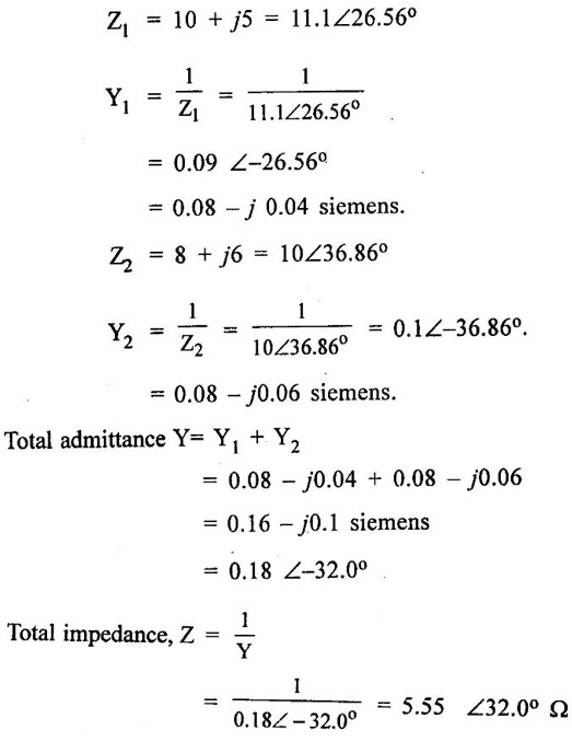
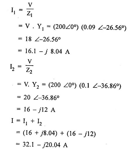
PARALLEL RLC CIRCUIT Figure 1.72 shows a circuit which consists of complex impedance Z1, Z2 and Z3 connected in parallel across an ac voltage source V. It delivers a total current I to the impedances. Apply KCL to the circuit shown in figure 1.72. I = I1 + I2 + I3 Now I1 = Y1 × V I2 = Y2 × V I3 = Y3 × V where Y1 = 1/Z1, Y2 = 1/Z2, Y3 = 1/Z3 are complex admittances of the three impedances. Then, Therefore, the equivalent complex admittance for a parallel circuit may be obtained by addition of all complex admittances in parallel and reciprocal of equivalent complex admittance is equivalent complex impedance. Problem 1.17 An ac circuit consists of a pure resistance of 10Ω and is connected to an ac supply of 230 V, 50 Hz. Calculate the (i) current (ii) power consumed and (iii) equations for voltage and current. Solution : Problem 1.18 A pure inductive coil allows a current of 10A to flow from a 230 V, 50 Hz supply. Find (i) Inductance of the coil, (ii) Power absorbed (iii) equations for voltage and current. Solution : Voltage equation, V = Vm sin ωt = 325.25 sin 314 t Current equation Problem 1.19 A 318 μF capacitor is connected across 230 V, 50Hz system. Find (i) the capacitive reactance (ii) rms value of current (iii) equations for voltage and current. Solution : Problem 1.20 A capacitor having a capacitance of 10 μF is connected in series with a non-inductive resistance of 100Ω across a 100V 50 Hz supply. Calculate (a) current (b) Phase difference between the current and supply voltage (c) Power. Solution : Problem 1.21 A resistor R is connected in series with a capacitor C, and combination is connected across 100V, 50Hz supply. The voltage drop across resistor is 60V and the power dissipated in the resistor is 108 W. Find R and C. Solution : Voltage drop across resistor VR = 60V Current through series circuit = I I2R = 108 Problem 1.22 A series RL circuit has risistance of 25Ω and inductance of 0.05H and is connected to 250 Volts, 50Hz source. Calculate the impedance, current, powerfactor and power. Solution: XL = 2πfL = 2π × 50 × 0.05 = 15.708 Ω Impedance: Z = R + jXL = 25 + j 15.708 = 29.52 ∠32.14° (b) Current: (c) Power factor = cos ϕ = cos (32.14°) = 0.846 (lag) where current lags behind the voltage, so that we should mention 'lag' here. Power consumed = |V| |I| cos ϕ = 250 × 8.468 × 0.846 = 1790.982 watts. Problem 1.23 A series RL circuit has resistance of 75Ω and inductance of 318 mH. This circuit is supplied from a 50Hz source and the voltage across the 75Ω resistor is found to be 150 V. Calculate the supply voltage and phase angle. Solution: By Ohm's law, VR = IR To find supply voltage, we need to find voltage across inductor and resistor (VR is given) Inductive reactance, XL = 2πfL = 2π × 50 × 318 × 10-3 = 99.9 Ω = 100 Ω Voltage across inductor VL = IXL = 2 × 100 = 200 V Problem 1.24 A resistance of 12Ω, an inductance of 0.15 H and a capacitance of 100 HF are connected in series across a 100V, 50Hz supply. Calculate the current, phase difference between current and supply voltage, power consumed. Draw the vector diagram of supply voltage and line current. Solution : R = 12 Ω, L = 0.15 H, C = 100 μF = 100 × 10-6 F Inductive reactance XL = 2πf L = 2π × 50 × 0.15 = 47.1 Ω Current I: To find Z Therefore current lags supply voltage by 52°. Power consumed (P) : P = VI cos ϕ = 100 × 5.15 × cos 52° = 317.1 watts. Problem 1.25 A resistance of 25 Ω conductance of 0.2 H and a capacitance of 100 μF are connected in series across 220 V, 50 Hz supply. Find (a) impedance (b) current (c) voltage across R, L and C. (d) Power in watts and VA (e) Power factor and angle of lag. Solution : R = 25 Ω, L = 0.2H, C = 100 μF = 100 × 10-6 F (d) Power in VA = V × I = 220 × 5.5 = 1210 Problem 1.26 In an RLC circuit, pure resitance of 40 Ω, pure inductance of 50 mH and a capacitor connected across 400 V, 50Hz ac supply. RLC circuit draws current of 10 A. Determine power factor of circuit and capacitor value. Solution : where XL = 2πfL = 2π × 50 × 50 × 10-3 = 15.7 Ω so equation (1) becomes Problem 1.27 A coil having resistance of 7Ω and an inductance of 31.8 mH is connected to 230 V, 50 Hz supply. Calculate (i) the circuit current (ii) phase angle (iii) power factor (iv) power consumed. Solution : XL = 2πfL = 2 × 3.14 × 50 × 31.8 × 10-3 = 10 Ω Problem 1.28 A 200 V, 50 Hz inductive circuit takes a current of 10A, lagging 30 degree. Find (i) the resistance (ii) reactance (iii) inductance of the coil. Solution : Problem 1.29 A capacitor of capacitance, 79.5 μF is connected in series with a non inductive resistance of 30Ω across a 100V, 50 Hz supply. Find (i) impedance (ii) current (iii) phase angle (iv) Equation for the instantaneous value of current. Solution: ω = 2πf = 2 × 3.14 × 50 = 314 rad/sec i = 2.828 sin (314 t + 53°) Problem 1.30 A 230 V, 50Hz ac supply is applied to a coil of 0.06 H inductance and 2.5Ω resistance connected in series with 6.8 uF capacitor. Calculate (i) Impedance, (ii) Current (iii) Phase angle between current and voltage (iv) Power factor (v) Power consumed. Solution : XL = 2πfL = 2 × 3.14 × 50 × 0.06 = 18.84 Ω Problem 1.31 A coil of power factor 0.6 is in series with a 100 uF capacitor. When connected to a 50 Hz supply, the potential difference across the coil is equal to the potential difference across the capacitor. Find the resistance and inductance of the coil. Solution : Problem 1.32 A current of (120 – j50)A flows through a circuit when the applied voltage is (8 + j 12) V. Determine (i) impedance (ii) Power factor (iii) power consumed and reactive power. Solution : Problem 1.33 Two impedance given by Z1 = 10 + j5 and Z2 = 8+ j6 are connected in parallel and connected across a voltage of v = 200 + j0. Calculate the circuit current, its phase and branch currents, power factor, and power. Solution : Currents Power factor = cos (angle between V and I) = cos (32°) = 0.848 (lag) Power = |V||I| cos ϕ = 200 × 36 × 0.848 = 6105.6 watts. Problem 1.34 An impedance of (7 + j5) Ω is connected in parallel with another circuit having impedance of (10 – j8) Ω The supply voltage is 230 V, 50 Hz. Determine, admittance, total current taken from the mains and powerfactor. Solution : Z1 = 7 + j5 = 8.6 ∠ 35.53° Current taken from the supply voltage (I) = V. Y = 230 ∠ 0° × 0.13 ∠ -8.74 = 29.9 ∠ -8.74° Power factor = cos ϕ = cos (-8.74°) = 0.988 lagging since ϕ is negative.


Basic Electrical and Electronics Engineering: Unit I: Electrical Circuits : Tag: : with Solved Example Problems - Parallel RLC Circuit
Related Topics
Related Subjects

Basic Electrical and Electronics Engineering
BE3251 2nd semester Mechanical Dept | 2021 Regulation | 2nd Semester Mechanical Dept 2021 Regulation

Basic Electrical and Electronics Engineering
BE3251 2nd Semester CSE Dept 2021 | Regulation | 2nd Semester CSE Dept 2021 Regulation