Engineering Physics: Unit III: b. Optics
Michelson's Interferometer
Operational Principle, Construction, Diagram, Working, Formation of fringes, Types of Fringes, Applications
SOLVED PROBLEMS of Optics: Engineering Physics: Optics
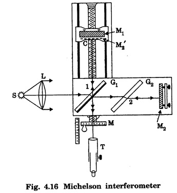
MICHELSON'S INTERFEROMETER Two interfering beams are formed by splitting the light from a source into two parts by partial reflection and refraction. These beams are sent in two perpendicular directions, and they are finally brought together after reflection from plane mirrors to produce interference fringes. Michelson interferometer is shown in fig 4.16. The apparatus consists of two highly polished plane mirrors M1 and M2. The mirrors are mounted vertically on two arms perpendicular to each other. The mirror M1 is mounted on a carriage C so that it can be moved forward and backward. The distance moved by this mirror can be accurately measured with the help of a graduated drum fitted on the micrometer screw M. The mirror M2 is fixed. There are two plane parallel glass plates, G1 and G2 of same thickness placed at an angle of 45° to the incident beam. The plate G2 is semi-silvered on its back side and acts as a beam splitter, i.e., a beam incident on it is partially reflected and partially transmitted. The plate G2 is a compensating glass plate. S is a monochromatic light source. A telescope (T) is positioned perpendicular to M1 to receive rays reflected from both M1 and M2. Light from source S is rendered parallel by means of a collimating lens L. This light is made to fall on a semi-silvered glass plate G1. The light beam is divided into two parts. One part of the light is reflected to travel towards mirror M1 (ray 1) while the other part of the light is transmitted towards M2 (ray 2). These light rays fall normally on mirrors M1 and M2 and are reflected back along its original paths. The light reflected by mirror M1 passes through G1 to reach the telescope T. The ray reflected by mirror M2, on reaching G1, gets reflected at its semi-silvered surface to reach the telescope. A path difference can be introduced between the two reflected rays by moving mirror M1. If we look through the telescope in the direction of mirror M1, we can see mirror M1 directly together with a virtual image of M2, denoted by M'2 formed close to M1 by reflection in the glass plate G1. Hence, the rays reaching the telescope appestr to travel from M1 and M'2. Thus, Michelson interferometer system is optically similar to the interference from an air film enclosed between M1 and M'2. The interference fringes may be straight, circular or parabolic etc., depending upon • path difference and • angle between mirror M1, and virtual mirror M'2. Function of the compensating plate G2 The ray reflected at M1 passes through glass plate G1 twice and reaches the telescope, while the ray reflected at M2 does not pass even once. That is why a second plate (G2) made with same material, thickness and inclination as G1 is introduced along the path of the ray travelling towards M2. Thus, the function of plate G2 is just to equalise the optical paths travelled by both rays. • One of the interfering beams comes from M1 and the other appears by reflection from the virtual image of mirror M2, i.e., M'2. •
An air film is enclosed between the two mirrors M1 and M •
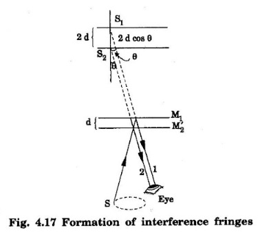
The two interfering beams appear from two virtual images S1
and S2 of the light source S as shown in fig. 4.17. •
Let S1 and S2 be two virtual sources. The
distance S1 between the virtual sources is 2d. As ray 2 coming after
reflection from M2, suffers reflection at the silvered
surface of glass plate G1, an additional path difference of λ/2
is introduced between the two rays. •
If we observe in the direction making an angle 'θ' with the normal to the
mirrors, the total path difference is 2d cos θ + λ/2 (Fig. 4.17). •
For maximum intensity in the fringes, 2d
cos θ + λ/2 = nλ
where
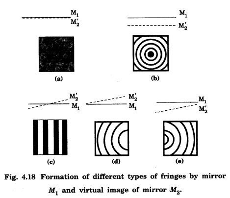
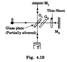
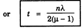
n = 0, 1, 2, ... Case 1: When M'2 coincides with M1 i.e., the paths are exactly equal, the path difference is only λ/2. Therefore, the field of view is perfectly dark as shown in fig 4.18(a). Case 2: M1 is moved either forward or backward parallel to itself. Now, mirror M1 is exactly perpendicular to mirror M2, i.e., mirror M1 and virtual mirror M'2 are parallel. When an air film of constant thickness is enclosed between mirrors M1 and M'2 we observe sufficiently spaced circular fringes as shown in fig. 4.18(b). Case 3: When mirror M1 intersects the virtual image M'2, the air film enclosed is wedge shaped, and straight line fringes are produced as shown in fig. 4.18(c). If virtual image M'2 lies just above the plane of mirror M1 and they are not perfectly parallel, the fringes produced are curved as shown in fig. 4.18(d). If the plane of mirror M1 lies above the plane of virtual image M'2 and they are not perfectly parallel, the fringes formed are slightly curved as shown in fig. 4.18(e). It is used to find (i) the wavelength of a given light source. (ii) the refractive index and thickness of a transparent material (iii) the resolution of wavelengths (iv) the standardisation of metre Using monochromatic light of unknown wavelength λ, Michelson's interferometer is adjusted for circular fringes. The position of mirror M1 is adjusted till a particular bright fringe coincides with the cross wire. Now, micrometer screw reading is noted. When mirror M1 is slowly moved, the number of fringes n that moved across the field view of the telescope is counted. This may be in the order of 20 or 30 fringes. Again micrometer screw reading is noted. The distance d moved by the mirror is given by the difference between initial and final micrometer screw readings. When mirror M1 is moved through a distance λ/2, the path difference changes by λ. The position of a particular bright fringe across the cross wire is replaced by the next bright fringe. For one fringe shift, the distance moved by the mirror M1 is λ/2 (half of the wavelength). Let mirror M1 move through distance d and the number of fringes that crosses the field of view be n. For the shift of n fringes, distance moved by mirror M1 = d = nλ/2 Knowing d and n, the wavelength of monochromatic light λ can be calculated. For this purpose, a thin film of refractive index μ is introduced in the path of one of the interfering beams (Fig. 4.19). If the thickness is t, then the path of the beam is increased by (μ - 1). Therefore, the path difference between the beams becomes 2 (μ - 1)t. Suppose due to this path difference, n fringes move across the field of view. Then, 2(μ - 1) t = nλ If μ, n and λ are known, thickness t can be calculated.Principle
Construction
Working
Formation of fringes
Types of Fringes
Applications of Michelson's Interferometer
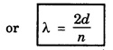
Wavelength Determination
Determination of Thickness of a Thin Transparent Sheet
Engineering Physics: Unit III: b. Optics : Tag: : Operational Principle, Construction, Diagram, Working, Formation of fringes, Types of Fringes, Applications - Michelson's Interferometer
Related Topics
Related Subjects

Engineering Physics
PH3151 1st semester | 2021 Regulation | 1st Semester Common to all Dept 2021 Regulation