Manufacturing Technology: Unit V: Programming of CNC Machine Tools
manual part programming
Programming of CNC Machine Tools - Manufacturing Technology
To prepare a part program using a manual method, the programmer writes the machining instructions on a special format called part programming manuscript.
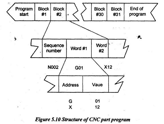
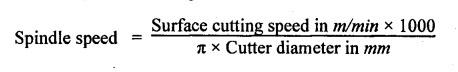
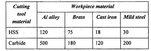
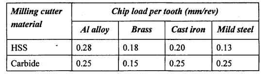
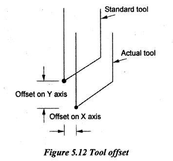
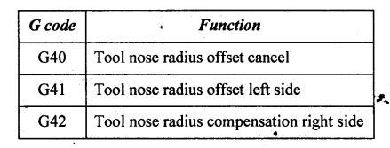
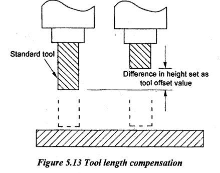
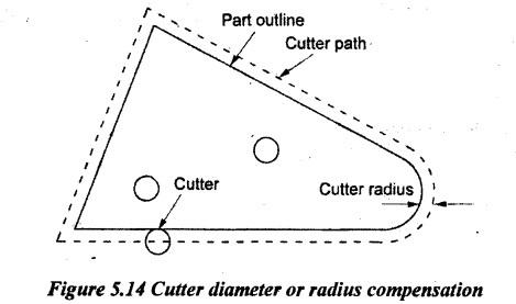
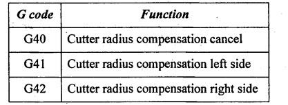
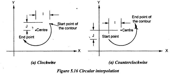
MANUAL PART PROGRAMMING To prepare a part program using a manual method, the programmer writes the machining instructions on a special format called part programming manuscript. The programmer first prepares the program manuscript in a standard format. The instructions must be prepared in a very precise manner because the typist prepares NC tapes directly from the manuscript. Manuscripts come in various forms depending on the machine tool and tape format to be used. The manuscript is the relative tool and workpiece locations. It includes the preparatory functions, miscellaneous instructions and speed/feed specifications which are needed to operate the machine under the tape control. Complex shaped components require tedious calculations. Manuscripts are typed with a device known as Flexowriter or similar tape-punch device which is also used to type the program instructions. After the program is typed, the punched tape is prepared on the flexowriter. The program can also be prepared microprocessor based terminals or microcomputers and then be stored or transmitted directly to the machine tools. Figure 5.9 shows the block diagram of manual part programming. To be able to create a part program manually, it needs the following information: (a) Knowledge about various manufacturing processes and machines. (b) Sequence of operations to be performed for a given component. (c) Knowledge of the selection of cutting parameters. (d) Editing the part program according to the design changes. (e) Knowledge about the codes and functions used in part programs. The manual programming jobs can be divided into two categories. (i) Point-to-point jobs (ii) Contouring jobs. Except for complex work parts with many holes to be drilled, the manual programming is ideally suited for point-to-point applications. On the other hand, except for the simplest milling and turning jobs, the manual programming can become quite time-consuming for the application requiring continuous path control of tool. So, contouring is much more suitable for computer-assisted part programming. Therefore, the manual part programming is used only for point-to-point operations. A CNC program consists of, blocks, words and addresses. Basically, the machine receives instructions as a sequence of blocks containing commands to set machine parameters, speed, feed and other relevant information. Each line of instruction is capable of specifying dimensional and non-dimensional data and it is written in a specific format. This format is known as NC block. Figure 5.10 shows the structure of the CNC part program. (a) Word: Each of the necessary instructions for a particular operation given in the part program is known as an NC word. A block is composed of one or more words. A word is composed of an identification letter and a series of numerals, for example, the command for a feed rate of 100 mm/min is F100. (b) Block: A block is equivalent to a line of codes in a part program. A group of such NC words constitutes a complete NC instruction, known as block. A command is given to the control unit using a block. Each block contains all the words in the same sequence for specifying the information related to machining. A block contains the following information: 1. Machining sequences such as classification of process, tool startup point, cutting depth, tool path, tool offsets, and tool corner wear compensation etc. 2. Cutting conditions such as spindle speed, feed rate, etc. 3. Selection of cutting tool 4. Other parameters such as coolant requirement, clamping, change of tool etc. (c) Address: The identification letter at the beginning of each word is called address. The meaning of the address is in accordance with EIA (Electronic Industries Association) standard RS-274-D. The most common 'addresses' are listed below: The detailed description of all the addresses and their meanings are given in further topics. The typical program format is N10 G01 X50 Y100 Z30 F100 $200 T02 M03. From above format, the following should be understood. (i) Sequence number (N Address): A sequence number is used to identify the block. It is always placed at the beginning of the block and it can be regarded as the name of the block. The sequence numbers need not be consecutive. The execution sequence of the program is according to the actual sequence of the block and not the sequence of the number. In fact, some CNC systems do not require sequence numbers. (ii) Preparatory function (G Address): A preparatory function determines how the tool is to move to the programmed target. Various preparatory functions used in programming are given in further topics. (iii) Co-ordinate word (X/Y/Z Address): A co-ordinate word specifies the target point of the tool movement (absolute dimension system) or the distance to be moved (incremental dimension). The word is composed of the address of the axis to be moved and the value and direction of the movement. For example, X100 Y200 represents the movement to (100, 200). To determine the sequence of positions and movements of the cutting tool relative to the workpiece, it is necessary to establish a standard axis system. The standard coordinate system is followed while developing the part program as given in Chapter 5.2.3 on Page 5.6. Whether the dimensions are absolute or incremental will have to be defined previously (using G90 or G91). G 90 for Absolute programming G 91 for Incremental programming (iv) Parameter for circular interpolation (I/J/K Address): These parameters specify the distance measured from the start point of the arc to the centre. Numerals following I, J and K are the X, Y and Z components of the distance respectively. (v) Spindle function (S Address): The spindle speed is commanded under an S address and it is always in revolution per minute. Normally, the speed in CNC machines refers to spindle speed whose unit is rpm. It can be calculated by the following formula. In programming, rpm should be noted as S (numerical value). For example, S200 means that the speed of the spindle is 200 rpm. The code of preparatory function used for spindle speed is G97. If the code of preparatory function used for spindle speed is G97 and cutting speed in m/min is given. The corresponding spindle speed will automatically be considered. The format used is G97 S250 which means setting spindle speed corresponding to the cutting speed of 250 m/min. The following table gives the surface cutting speeds in m/min for some common materials: (vi) Feed function (F Address): Feed is used to measure the distance travelled by the tool. The feed is programmed under an F address except for rapid traverse. For example, F100 represents a feed rate of 100 mm/min. The unit may be in mm per revolution (in the case of turning machine) or in mm per minute (in the case of milling machine). The unit of the feed rate has to be defined at the beginning of the program. The feed rate can be calculated by the following formula. Feed Rate = Chip load / tooth × Number of teeth × Spindle speed The following table gives the chip load per tooth of milling cutters cutting some common materials. (vii) Tool function (T Address): The selection of the tool is commanded under a T address. The cutting tool will be coded using 1-5 digit numbers. From this code, the respective tool and its position can automatically be identified and changed by means of a tool changer. For example, T121 means that the tool from station 1 is used having the second cutting edge. (viii)Miscellaneous function (M Address): The miscellaneous function is programmed to control the machine operation other than for coordinate movement. Various miscellaneous functions used in programming are given in further topics. The following steps should be kept in mind while writing the program. 1. Fixation of the coordinate system 2. Reference of G and M codes 3. Dimensions of work and tools 4. Locating the fixture and machine table 5. Speed and feed according to the work and tool material. The following is the procedure to be followed in CNC programming and machining. The most important point is to verify the program by test run it on the machine before the actual machining in order to ensure that the program is free of mistakes. 1. Study the part drawing carefully. 2. Unless the drawing dimensions are CNC adapted, select a suitable program zero point on the workpiece. The tool will be adjusted to this zero point during the machine setup. 3. Determine the machining operations and their sequence. 4. Determine the method of work clamping (vice, rotary table, fixtures etc.). 5. Select cutting tools and determine spindle speeds and feeds. 6. Write the program (translate machining steps into program blocks). If many solutions are possible, try the simplest solution first. It is usually longer but it is better to proceed in this way. 7. Prepare tool chart or diagram, measure tool geometry (lengths, radii) and note down, 8. Clamp workpiece and set up the machine. 9. Enter compensation value if necessary. 10. Check and test the program. It is a good practice to dry run the program (i) without the workpiece, (ii) without the cutting tools, or (iii) by raising the tool, to a safe height. If necessary, correct and edit program and check again. 11. Start machining. (i) Job dimension/workpiece (ii) Work holding (damping, In-chucking) (iii) Feed/cutting speed (iv) Finished dimension with tolerance (v) Sequence of operation (vi) Types of tools (vii) Mounting of tools. The NC system must know where the part is positioned in the workspace. The procedure for defining the Workpiece Coordinate (WPC) is called workpiece coordinate setting. Two important factors deal with workpiece coordinate setting are as follows: (i) where the part datum (the origin of the WPC) is situated with respect to the workpiece (ii) where the part datum is situated with respect to the machine tool. The methods for locating the positions of the WPC origin with respect to the machine tool vary for each machine tool. There are three methods of workpiece coordinate setting normally used: (a) Machine zero point (machine datum) reference (b) Workpiece origin reference (c) Tool home position reference. (a) Machine zero point (machine datum) reference: Machine zero point (machine datum) is a fixed point on the machine tool and it cannot be programmed or altered. The machine datum is fixed by the machine manufacturer. It cannot be altered by the programmer / user. It is used to calibrate the measuring system of NC machine tool. G54 code tells the machine where the position of the WPC is measured from the machine zero point. (b) Workpiece origin reference: The WPC origin may be located at any part of the workpiece but to avoid dimensional recalculations and respectively errors, the good programmers will choose the WPC origin at the point from where the part features are dimensioned as shown in Figure 5.11. (c) Tool home position reference: Another important point is the tool home position reference program start point (also). This point is selected by the programmer at some distance from the workpiece. It should not be too far to save some time when the tool returns home, and not too close to allow for safe indexing of the tool turret when the cutting tool is changed. The program, therefore, the new part machining, starts and ends with the tool at home position but the tool needs also to be returned to home whenever a tool change takes place during the program execution. 1. Tool Offset A part program is generated by keeping in mind a tool of a particular length, shape and thickness as a reference tool. But during the actual mounting of tools on the machine, different tools of varying lengths, thickness and shapes may be available. A correction for the dimension of the tools and movements of the workpiece has to be incorporated to give the exact machining of the component. It is known as tool offset. It is the difference in the positions of the centre line of the tool holder for different tools and the reference tool. When a number of tools are used, it is necessary to determine the tool offset of each tool and store it in the memory of the control unit. Figure 5.12 explains the function of the tool offset. Tool offset is instated with the following G code functions. Normally, it is found that the size of the workpiece (diameter or length) is not within tolerance due to wear of the tool. It is the possible to edit the value of offsets to obtain the correct size. It is known as tool wear compensation. 2. Tool Length Compensation The setting of the depth of the tool to an exact is very difficult and time-consuming. Therefore, it may be convenient to set the tool to an approximate dimension and then it adjusts the difference by some external means switches on control systems. This procedure is called tool length compensation. Figure 5.13 describes the tool length compensation. It allows the programmer to ignore the precise length of each tool as a program is written. CNC system facilitates this feature. These practices are found very useful when the tool needs to be replaced and then the machine instructions need not be changed and only the difference in two dimensions is fed through the switches. Further, this facility can usefully be employed to program a number of tools with the same instructions for tool travel. Tool length compensation is instated with a G43 code. 3. Cutter Radius or Diameter Compensation In profile milling operations, it is essential to calculate the tool path for preparing the program. This path refers to the spindle axis which is away from the profile required. When constructing the tool path, the basic factor to be considered is the size of the cutting tool. The actual tool path is different from the part outline because the tool path is the path taken by the center of the cutter. It is at the periphery of the cutter that the machining takes place. The purpose of the cutter radius offset is to offset the tool path from the desired part surface by the radius of the cutter. This means that the part programmer can define the exact part outline in his geometry statements. The cutter radius offset is illustrated in Figure 5.14. In Figure 5.14, in order to cut a workpiece indicated as a part outline with the cutter of a particular radius, the path for the centre of the tool must be separated by the distance equal to the cutter radius from the part outline. The cutter radius compensation is instated with the following G code functions. It is to command the cutter to move from the existing point to the target point at the fastest speed of the machine. G00 code is used for rapid positioning of the tool. To the possible extent, all idle movements are programmed with G00. For example: 1. Movement from machine reference point to turret index position. 2. Movement from turret index point to safe positioning point before cutting and after cutting. 3. All idle movements when the tool is away from the component. The calculation of successive increments in slide position to reach the programmable point is called interpolation. It is the process of developing coordinate points between start and finish coordinates. Interpolation in NC machining is required to calculate the intermediate points of a curve or straight line when its start and end coordinates are given. Interpolation may be linear, circular or cubic/parabolic. The type of interpolation used in NC machine depends on which the given profile is approximated with the help of a straight line, arcs of circles or segments of the parabola. There are three types of interpolation are used in CNC machining. They are as follows: 1. Linear interpolation (G01 code is used in part program) 2. Circular interpolation (G02, G03 codes are used in part program). 3. Cubic/Parabolic interpolation. 1. Interpolator Mostly, contouring systems are done by an interpolator. The two types of interpolators used are given below. 1. External interpolator 2. Internal interpolator. External interpolation means that crowding the points on punched tape (or) program and giving an instruction of the velocity in each axis and changing this from point to point. Internal interpolation is a general instruction given by the program to follow a specified curve between two points widely spaced. 2. Linear Interpolation Linear interpolation is mostly used approximate straight lines. Consider the interpolation of a straight line AB shown in Figure 5.15 having (x1, y1) as starting point and (x2, y2) as the end point. The coordinates of successive intermediate points are calculated from the consideration that distances (x2 − x1) and (y2 — y1) must be traversed in equal time. It implies that the cutting tool should move along line AB at a constant speed. Linear interpolation can also be employed to approximate the curved profiles. In this process, the curve is represented as a series of finite straight line increments. The length of these finite increments should be such that the profile obtained by their sequential joining fits the curve within the required tolerances. Linear interpolation is instated with a G013 code. 3. Circular Interpolation Circular interpolation is mostly used in machining of circles, arcs of circles and profiles consisting of different radii. For machining an arc using this method, the coordinates of the starting and end points of the arc, radius of the circle, coordinates of the centre and direction of movement need to be programmed. The circular interpolation is similar to linear interpolation in such a way that the circular interpolation does also break the arc profile into extremely small straight lines. However, the operational difference is significant as the required number of coordinates is calculated in the case of circular interpolation by the interpolator which generates the controlling signals that move the cutting tool along the programmed arc.. NC systems are capable of commanding a circular motion. Arc movement is known as circular interpolation and ii is carried out with a G02 (clockwise circular interpolation) or G03 (counterclockwise circular interpolation) codes. The arc radius is specified either by the incremental dimensional words I, J and K or directly by the radius R-code. The words I, J and K defines the position of arc centre point with respect to the arc start point. I is the distance along X axis, J is along Y axis, and K is along Z axis. This parameter is defined as the vector (magnitude and direction) from the starting point to the centre of the arc. If R-code is used, arcs less than 180° are given a positive radius and arcs more than 180° are given a negative radius value. In both methods, the program block which starts with a G02 or G03 codes must also include the coordinates of the arc end point. 4. Cubic/parabolic Interpolation Parabolic interpolation is particularly suitable in machining complicated profiles which are free-formed as in the automotive or aeronautical industries. The cubic interpolation is based on the parabolic equation which is very flexible and it can be made to fit almost to any curve. The parabolic interpolation can be employed in two modes such as tangent and three- point. The tangent parabola is tangent to the curve at the beginning and end of the span. The three-point parabola joins three non-linear points on the curve in a trajectory which is either a complete parabola or a part of it. In the first method, the maximum error occurs at the middle of the span whereas it occurs half way between middle and starting or end points in the second case.
1. Structure of Part Program
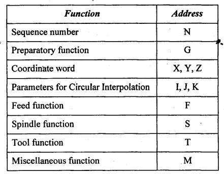
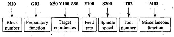
2. Important Terms Used in Part Programming
3. Steps for CNC Part Programming
4. Data Required for Part Programming
5. Work Coordinate Setting

6. Tool Information in Part Programming
7. Rapid Positioning in Part Programming
8. Interpolation in Part Programming

Manufacturing Technology: Unit V: Programming of CNC Machine Tools : Tag: : Programming of CNC Machine Tools - Manufacturing Technology - manual part programming
Related Topics
Related Subjects

Manufacturing Technology
ME3493 4th semester Mechanical Dept | 2021 Regulation | 4th Semester Mechanical Dept 2021 Regulation