Basic Electrical and Electronics Engineering: Unit I: Electrical Circuits
Kirchoffs Law
Equation, Example with Circuit Diagram, Applications, Problems with solution
The sum of currents entering a junction is equal to the sum of the currents leaving the junction.
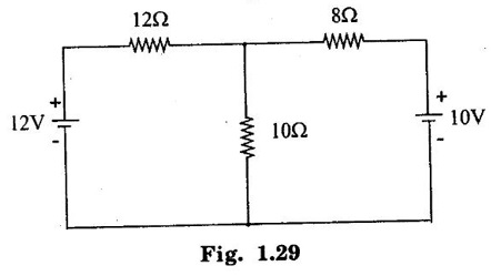
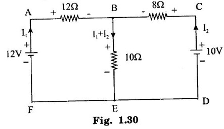
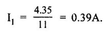
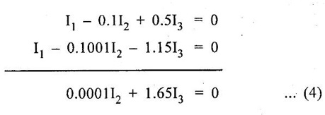
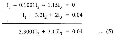
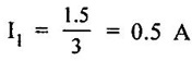
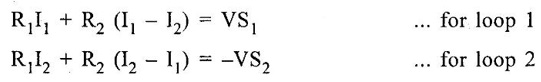
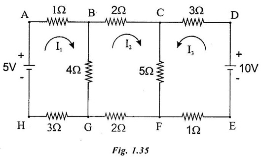
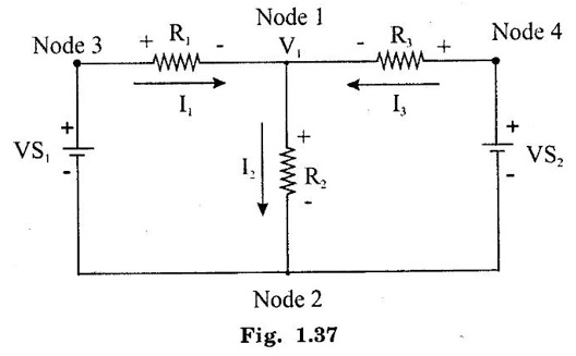
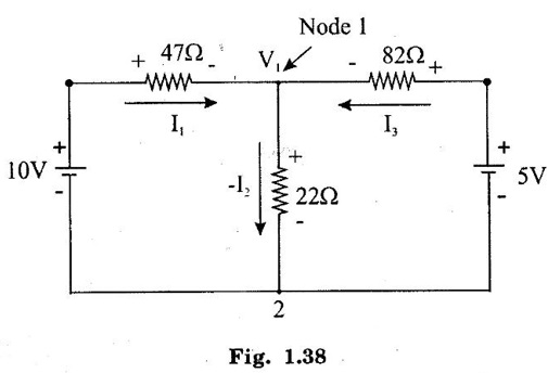
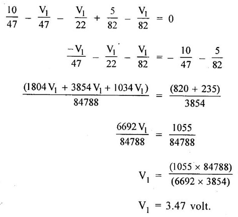
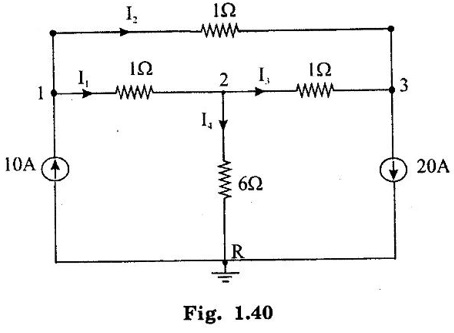
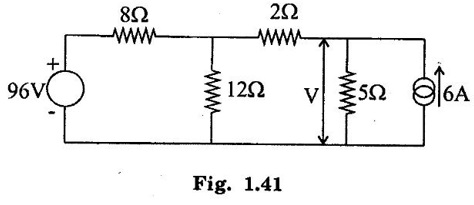
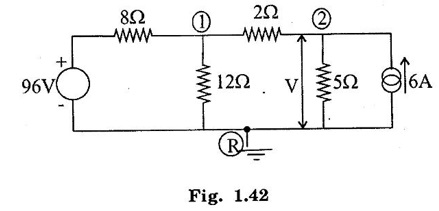
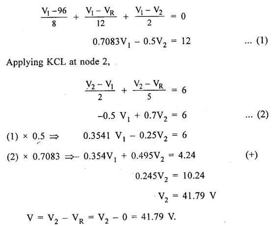
KIRCHOFFS LAW 1. Kirchoffs Point Law (or) Current Law (KCL) The sum of currents entering a junction is equal to the sum of the currents leaving the junction. If the currents towards a junction are considered positive and the currents away from the same junction negative, then this law states that the algebraic sum of all currents meeting at a junction is zero. Σ Current entering = Σ Currents leaving I1 + I3 = I2 + I4 + I5 (or) I1 + I3 - I2 - I4 - I5 = 0 2. Kirchoff's Mesh Law (or) Voltage law (KVL) The sum of the emf's (rises of potential) around any closed loop of a circuit equals the sum of the potential drops in that loop. Consider a rise of potential as positive and a drop of potential as negative, the algebraic sum of potential differences around a closed loop of a circuit is zero. ΣΕ - Σ IR drops = 0 (around closed loop) ΣΕ = Σ IR (or) Σ Potential rises = Σ Potential drops 3. Applications of Kirchoff's Laws Kirchoff's laws may be employed in the following methods of solving networks: 1. Branch-current method 2. Maxwell's loop (or mesh) current method 3. Nodal voltage method. 1. Branch-Current Method For a multi-loop circuit the following procedure is adopted for writing equations: 1. Assume currents in different branch of the network. 2. Write down the smallest number of voltage drop loop equations so as to include all circuit elements; these loop equations are independent. 3. Solve the above equations simultaneously. The assumption made about the directions of the currents initially is arbitrary. In case the actual direction is opposite to the assumed one, it will be reflected as a negative value for that current in the answer. The branch-current method (the most primitive one) involves more labour and is not used except for very simple circuits. Problem 1.6 In the circuit of figure 1.29, find the currents through each resistor and voltage drop across each resistor. Solution : The above circuit diagram can be redrawn as fig. 1.30. Apply KVL to ABEFA, we get, 12I1 + 10 (I1 + I2) = 12 12 – 12I1 - 10 (I1 + I2) = 0 −22 I1 − 10 I2 + 12 = 0 11 I1 + 5 I2 - 6 = 0 .... (1) Apply KVL to circuit BCDEB, we get, 8 I2 + 10 (I1 + I2) = 10 10 I1 + 18 I2 - 10 = 0 5 I1 + 9 I2 - 5 = 0 .... (2) multiply equation (1) by 5 and equation (2) by 11. Substituting value of I2 in equation (1) 11 I1 + 5 I2 - 6 = 0 11 I1 + 5 × (0.33) - 6 = 0 11 I1 + 1.65 – 6 = 0 11 I1 = 4.35 Current through 12 Ω resistor is I1 = 0.39 A Current through 8 Ω resistor is I2 = 0.33 A Current through 10 Ω resistor is I1 + I2 = 0.72 A The voltage drop across 12 Ω resistor = 0.39 × 12 = 4.68 V 8Ω resistor = 0.33 × 8 = 2.64 V 10Ω resistor = 0.72 × 10 = 7.2 V Problem 1.7 Find the current in the galvanometer arm of the Wheatstone bridge as shown in figure 1.31. Solution : Applying KVL in loop ABDA -1000I1 - 500 I3 + 100I2 = 0 divide above equation by -1000 I1 - 0.112 + 0.5I3 = 0 …. (1) In BCDB loop, −9990 (I1 − I3) + 1000 (I2 + I3) + 500I3 = 0 -9990 I1 + 1000 I2 + 11490 I3 = 0 divide above equation by -9990, I1 - 0.1001I2 - 1.15I3 = 0 ….. (2) In ADCEA loop, -100 I2 – 1000 (I2 + I3) + 20 − 500 (I1 + I2) = 0 - 500 I1 - 1600 I2 – 1000I3 = -20 divide the above equation by -500 I1 + 3.2 I2 + 2I3 = 0.04 …. (3) (1) - (2), (2) - (3), Solving equation (4) & (5), we get I3 = -0.735 μA Hence, the current in the galvanometer arm = 0.735 μ. Problem 1.8 Determine the current I1, I2 and I3 of the network shown in figure 1.32. Solution : Applying KVL in loop ABDA, 3I1 – 4I2 + 8I3 = 0 …… (1) In loop BCDB, 5 (I1 - I3) - 3 (I2 + I3) − 8 (I3) = 0 5I1 – 5I3 – 3I2 – 3I3 – 8I3 = 0 5I1 – 3I2 – 16I3 = 0 ….(2) In loop ADCEA, 4I2 + 3 (I2 + I3) = 2 7I2 + 3I3 = 2 ….(3) Multiplying equation (1) by 5 and equation (2) by 3, From equation (3) From (1) 7I2 + 3 (I3) = 0 7I2 + 3 (−0.037) = 2 7I2 + (-0.111) = 2 7I2 = 2.111 I2 = 0.301 A From (1), 3I1 – 4I2 + 8I3 = 0 3I1 – 1.204 - 0.296 = 0 3I1 -1.5 = 0 3I1 = 1.5 In the mesh current method, loop currents are used instead of branch currents. A branch current is the actual current through a branch. An ammeter placed in a given branch will measure the branch current. Loop currents are different because they are mathematical quantities that are used to make circuit analysis somewhat easier than branch current method. A systematic method of mesh analysis is listed in the following steps and is illustrated in figure. Step 1: Assign a current in the clock wise (CW) directions around each closed loop. This may not be the actual current direction. Step 2: Indicate the voltage drop polarities in each loop based on the assigned current direction. Step 3: Apply Kirchoff's voltage law around each closed loop. When more than one loop current passes through a component; include its voltage drop. This results in one equation for each loop. Step 4: Using substitution, solve the resulting equations for the loop currents. Circuit for Demonstrating mesh analysis Step 1: The loop currents I1 and I2 are assigned in the CW direction as shown in figure 1.33. Step 2: The Polarities of the voltage drops across R1, R2 and R3 are shown based on the loop current directions. Notice that I1 and I2 flow in opposite directions through R2 because R2 is common to both loop. Therefore, two voltage polarities are indicated. In reality, R2 currents can be separated into two parts, but remember that the loop currents are basic mathematical quantities used for analysis purposes. The polarities of voltage sources are fixed and are not affected by the current assignments. Step 3: Kirchoff's voltage law applied to the loop results in the following two equations. Step 4: The like terms in the equations are combined and rearranged for convenient solution so that they have the same position in each equation, that is, the Il to is first and the I2 term is second. The equations are rearranged into the following form. Once the loop currents are evaluated, all of the branch currents can be determined. The format for setting up the equation for a loop circuit can be stated as follows. 1. Sum the resistances around the loop, and multiply by the loop current. 2. Subtract the common resistance times the adjacent loop current sign of the source voltage. 3. Set the terms in steps 1 and 2 equal to the total source voltage in the loop is positive, the assigned loop current flows out of its positive terminal, the sign is negative if the loop current flows into its positive terminal. 4. Rearrange the terms so that like terms appear in the same position in each equation. Problem 1.9 Find the currents in all branches of the network shown in figure 1.34. Solution : Mark the nodes ABCDEFGH in the given circuit 1.35. Apply KVL in loop ABGHA 1 × I1 + 4 (I1 - I2) + 3I1 = 5 I1 + 4I1 – 4I2 + 3I1 = 5 8I1 – 4I2 = 5 …... (1) Apply KVL in loop BCFGB, 2 × I2 + 5 (I2 + I3) + 2 I2 + 4 (I2 – I1) = 0 2 I2 + 5 I2 + 5 I3 + 2 I2 + 4 I2 - 4 I1 = 0 -4 I1 +13 I2 + 5 I3 = 0 …... (2) Apply KVL in loop CDEFC, I3 = 1.3176 A Substitute I3 value in equation (3) 5I2 + 9 × 1.3176 = 10 5 I2 = -1.8584 I2 = -0.371 A Substitute I2 value in equation (1) 8 I1 - 4. (-0.371) = 5 8 I1 + 1.484 = 5 8 I1 = 3.516 I1 = 0.4395 = 0.44 A. Problem 1.10 Determine the current various resistors in the circuit shown in figure 1.36. Solution: The loop currents for the given figure. 104I2 - 86 × (-0.584) = 66 104 I2 + 50.224 = 66 104 I2 = 15.776 I2 = 0.151 A. Substitute I2 and I3 in equation (1) 7 I1 − 0.151 - 2 × (-0.584) = 24 7 I1 - 0.151 + 1.168 = 24 7 I1 = 24 - 1.017 7 I1 = 22.983 I1 = 3.283 A. Another alternate method of analysis of multiple loop circuits is called the nodal voltage method. It is based on finding the voltages at each node in the circuit using Kirchoff's current law. A node is the junction of two or more current paths. General Steps The general steps for the node voltage method are as follows: 1. Determine the number of nodes. 2. Select one node as a reference. All voltages will be relative to the reference node. 3. Assign current at each node where the voltage is unknown, except at the reference node. The directions are arbitrary. 4. Apply Kirchoff's current law to each node where currents are assigned. 5. Express the current equations in terms of voltages and solve the equations for the unknown node voltages. Circuit for Demonstrating node voltage analysis The figure 1.37 is used to illustrate the general approach to node voltage analysis. Step 1: Establish the node. In this case there are four nodes, as indicated in the figure 1.37. Step 2: Let's us node 2 as reference. Think of it as circuit ground. Node voltage 3 and 4 are already known to the source voltages. The voltage at node 1 is the only unknown it is designated as V1. Step 3: Arbitrarily assign the currents a node 1 as indicated in the figure 1.37. Step 4: The Kirchoff's current equation at node 1 is I1 = I2 + I3 = 0 Step 5: Express the currents in terms of circuit voltages using Ohm's law as follows. I1 =(VS1 - V1) / R1 I2 =V1/R2 I3 =(VS2-V1)/R3 Substituting these into the current equation, we get (VS1 - V1)/R1-V1/R2 +(VS2 − V1) / R3 =0 The only unknown is V1 ; so we can solve the single equation by combining and rearranging terms. Once the voltage is know, all branch currents can be calculated. Problem 1.11 Find the node voltages at node I as shown in figure 1.38. Solution: The unknown node voltage is V1, as indicated in figure 1.38. This is the only unknown voltage. Currents are assigned at node 1 as shown. The current equation is I1 − I2 + I3 = 0 Substitution for current using Ohm's law gives equation in terms of voltages Solving for V1 yields Problem 1.12 Find the current through 6Ω resistor in the circuit of the figure 1.39 by nodal method. Solution : Label the nodes as 1, 2, 3 and a reference node as shown in figure 1.40. Apply KCL at node 1, I1 + I2 = 10 Apply KCL at node 3 I3 + I2 – 20 = 0 Problem 1.13 Find voltage across 5 Ω resistor by nodal analysis. Solution: VR taken as zero. Apply KCL at node 1.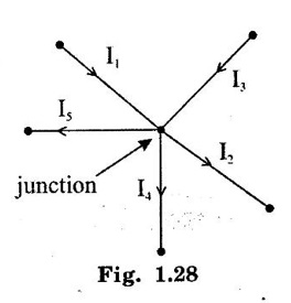


2. Mesh Current Method


 Substitute I3 in (4)
3. Nodal Voltage Method


Basic Electrical and Electronics Engineering: Unit I: Electrical Circuits : Tag: : Equation, Example with Circuit Diagram, Applications, Problems with solution - Kirchoffs Law
Related Topics
Related Subjects

Basic Electrical and Electronics Engineering
BE3251 2nd semester Mechanical Dept | 2021 Regulation | 2nd Semester Mechanical Dept 2021 Regulation

Basic Electrical and Electronics Engineering
BE3251 2nd Semester CSE Dept 2021 | Regulation | 2nd Semester CSE Dept 2021 Regulation