Engineering Physics: Unit III: b. Optics
Interference of light waves
This modification or change of intensity of light resulting from the superposition of two or more waves of light is called interference.
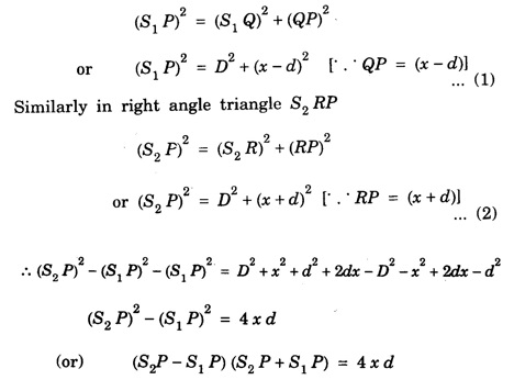
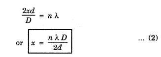
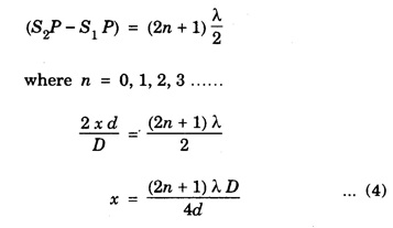
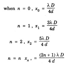
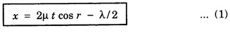
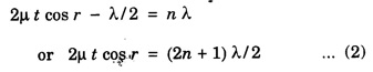
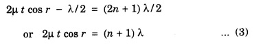
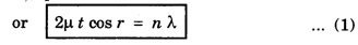
INTERFERENCE OF LIGHT WAVES When two light waves of the same frequency and having constant phase difference traverse simultaneously in the same region of a medium and cross each other then there is a modification in the intensity of light, in the region of superposition. This modification or change of intensity of light resulting from the superposition of two or more waves of light is called interference. At some points, where the crests of one wave falls on the crest of the other, resultant amplitude is maximum. Hence, the intensity of light is maximum. At certain other points, crest of one wave falls on trough of the other, therefore resultant amplitude becomes minimum and hence intensity of light is minimum. At the points, where the resultant intensity of light is maximum, the interference is said to be constructive. At the points where the resultant intensity of light is minimum, the interference is said to be destructive. In 1801, Thomas Young demonstrated successfully the phenomenon of interference of light by the double slit experiment, called Young's experiment. Consider a narrow monochromatic source S and two pin holes S1 and S2 equidistant from S. The pin holes provide the two point sources vibrating in the same shades. The two sources are separated at a distance 2d. Let a screen XY be placed at a distance D parallel to S1S2. The point O on the screen is equidistance from S1 and S2. Consider a point P at a distance x from O (Fig 4.9). We shall now consider the conditions for a bright or dark fringe at this point. From the right angled triangle S1 QP In Young's experiment, D is some thousand times greater than 2d or x so that if (S2 P + S1 P) is replaced by 2D, the error is not more than a fraction of one percent. Hence, Now, we shall consider the following two cases 1. Bright Fringes: The point P is bright when the path difference is a whole number multiple of wavelength λ, i.e. S2 P - S1 P = nλ where n = 0, 1, 2 Substituting the value of (S2 P - S1 P) from equation (1) we have Equating (2) gives the distances of the bright fringes from point O. At O, the path difference is zero hence there is a bright fringe. The next bright fringes are formed when n = 1, 2, 3 ...... and so on i.e. The distance between any two consecutive bright fringes is, 2. Dark Fringes: The point P is dark when the path difference is an odd number multiple of hall wavelength i.e. The equation (4) gives the distances of the dark fringes from point O. The dark fringes are formed as follows. The distance between any two consecutive dark fringes is, Hence the spacing between any two consecutive maximum or minima is the same. This is expressed by It is obvious that the spacing is directly proportional to and inversely proportional to. 2d. Conditions for Interference of light (i) Conditions for sustained interference (a) The sources should be coherent. (b) The sources should emit continuous waves of the same wavelength and time period. (ii) Conditions for observations (a) The separation between the two sources (2d) should be small. (b) The distance 'D' between two sources and the screen should be large. (c) The background should be dark. (iii) Conditions for good contrast (a) The amplitudes of the interfering waves should be equal or nearly equal. (b) The sources must be narrow, i.e., they must be extremely small. (c) The sources should be monochromatic. There are normally two methods for obtaining interference pattern. 1. Interference by Division of Wavefront Here the original wave is divided into two parts by using slits, prism or mirror, and the two wavefronts thus produced are brought together to produce the interference pattern. It requires a narrow source of light. Examples: Fresnel's Biprism, Lloyd's Mirror. 2. Interference by Division of Amplitude In this case the original amplitude of the wave is divided into two parts by reflection or refraction and the divided parts are finally brought close together to produce the interference pattern. It requires a wide source of light. Examples: Air wedge, Newton's Rings, Michelson Interferometer. Light reflected from soap bubbles, oil films etc., shows the interference effect. These very thin films have a thickness just a few times the wavelength of light, and hence it is called thin film interference. A plane light wave that falls on the film is reflected from the upper and lower surfaces, and the reflected beams interfere with each other. Thus, thin film interference is due to multiple reflections. Newton and Hooke observed and developed the interference phenomenon due to muitiple reflections from the surface of thin transparent materials. Thin layers of oil spread on water or any surface, heated metallic surfaces, soap bubbles etc. exhibit brilliant colours when light is incident on them. These colours of thin films are due to the interference of light between the light reflected from the front and back surfaces of the film. It is observed that interference in the case of thin film takes place due to 1. Reflected Light and 2. Transmitted Light Let ABCD (Fig.4.10) represent a thin transparent film (thickness t and refractive index μ) with the parallel boundary surfaces AB and CD. Let PQ be a light ray incident AB. The ray is partly reflected as RS and partly refracted as Q1 Q2 at Q1. The ray Q1 Q2 is again split up into a refracted ray P1 Q1, and a reflected ray Q2 Q3. The ray Q2 Q3 suffers reflection and refraction at Q3 and so on. If the thickness of the film is small, the directly reflected ray RS and the refracted ray R1 S1 from Q3 superimpose on one another. Therefore the waves of RS and R1 S1 are in a fit condition to interfere producing either brightness or darkness depending upon the path difference. The correct path difference between two reflected waves in this case is given by where, μ - refractive index of the medium t - thickness of the thin film r – angle of refraction λ - wavelength of the light 1. If the path difference x = n λ where n = 0, 1, 2, 3, 4. ... etc., constructive interference takes place and the film appears bright 2. If the path difference x = (2n + 1) λ /2 where n = 0, 1, 2 ... etc., destructive interference takes place and the film appears dark Here n is an integer only, therefore (n + 1) can also be taken as n where n = 0, 1, 2, 3, 4 ... etc. When the thickness of the film is small, the transmitted rays P1Q1 and P2Q2 (which are parallel) superimpose and interference of light occurs. The type of fringes (bright or dark) depends upon the path difference between these two rays. 1. The film will appear bright or constructive interference will form if the path difference x = n λ where n = 0, 1, 3, ......... etc. 2. The film will appear dark or destructive interference will form if the path difference x = (2n + 1) λ/2 2 μt cos r = (2n + 1) λ/2 ....(2) where n = 0, 1, 2, 3, ......... etc. With monochromatic light alternate bright and dark fringes are obtained. With white light the fringes obtained are coloured because the path difference 2 μt cos r depends upon μ, t and r. 1. If t and r are constant, the path difference varies with μ or the wavelength of light. Light light is composed of various colours. Therefore, these colours will appear in the order of violet, blue etc. as the wavelength λ increases. 2. If the angle of incidence changes, r also changes and hence the path difference also changes. Therefore, in various directions different colours will be seen with white light. 3. When the thickness of the film varies the film passes through various colours for the same angle of incidence.Theory of Interference Fringes


Position and Spacing of fringes


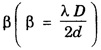 and it is known as fringe width.
Type of Interference
Thin film interference

1. Interference due to Reflected light

2. Interference due to transmitted light:
Colours in thin films:
Engineering Physics: Unit III: b. Optics : Tag: : - Interference of light waves
Related Topics
Related Subjects
Engineering Physics
PH3151 1st semester | 2021 Regulation | 1st Semester Common to all Dept 2021 Regulation