Hydraulics and Pneumatics: Unit I: Fluid Power Priniciples and Hydraulic Pumps
External Gear Pumps
Construction, Operation, Volumetric Efficiency, Advantages and Disadvantages
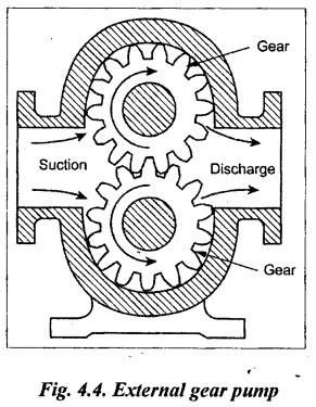
External gear pumps have two mating gears (driver and follower) that are turned in a closely fitted casing, as shown in Fig.4.4
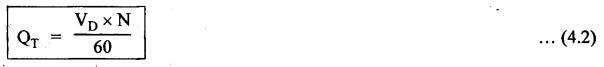
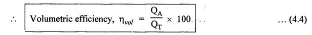
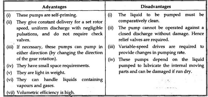
EXTERNAL GEAR PUMPS External gear pumps have two mating gears (driver and follower) that are turned in a closely fitted casing, as shown in Fig.4.4. Each gear is mounted on a shaft which is supported on bearings in the end covers. In these, the driver shaft is coupled to the prime mover (electric motor, gasoline engine, etc.). Two parts-inlet and delivery parts—are provided directly on the opposite sides of the mesh point of the gears. The larger and straight ports are preferred for for better performance. The driving shaft is usually connected to the upper gear of the pump. The rotation of the driver gear causes the follower gear to turn. The self-explanatory Fig.4.5 explains the operation of the external gear pump in steps. When the pump starts rotating, the rotation of gears forces air out of the casing and into the discharge pipe [Fig.4.5(a)]. This removal of air from the pump casing produces a partial vacuum on the suction side of the pump. Fluid from an external reservoir is forced by the atmospheric pressure into the pump inlet. Here the fluid is trapped between the teeth of the upper and lower gears and the pump casing [Fig.4.5(b)]. Continued rotation of the gears forces the fluid out of the pump discharge [Fig.4.5(c)]. The volumetric displacement and theoretical flow rate of a gear pump can be determined as follows: Let D1 = Inside diameter of gear teeth in m, Do = Outside diameter of gear teeth in m, L = Width of gear teeth in m, N = Speed of pump in rpm, VD = Volumetric displacement of the pump in m3/rev, and QT = Theoretical pump flow rate in m3/sec. If addendum and dedendum of a gear is known, then inside diameter of gear teeth can be calculated by Di = D。 - 2 (Addendum + Dedendum) The volumetric displacement, from the geometry of the gear teeth, is given by, Then the theoretical flow rate can be calculated as From equation (4.2), it is evident that the pump flow rate depends on : (i) Size of the gear, and (ii) Speed of the pump. Note If the gear is specified by its module and number of teeth, then the theoretical discharge can be found by using the following empirical relation : where L = Width of gear teeth in m, M = Module of gear in m, N = Pump speed in rpm, and z = Number of gear teeth. Obviously there will be a small radial clearance between the gear teeth and the casing so as to achieve the gears rotation. As a result, some of the fluid may leak inside the system without discharging at the outlet port. This internal leakage, also known as 'pump slippage', results in lesser flow rate (QA) than the theoretical flow rate (QT). This is represented by the volumetric efficiency. where QA and QT are actual and theoretical flow rate of the pump respectively. Since the internal leakage increases with the increase in discharge pressure, the volumetric efficiency will be lower for the high discharge pressure. Table 4.4 presents the merits and demerits of using the external gear pumps. Table 4.4. Advantages and disadvantages of external gear pumps Advantages (i) These pumps are self-priming. (ii) They give constant delivery for a set rotor speed, uniform discharge with negligible pulsations, and do not require check valves. (iii) If necessary, these pumps can pump in either direction (by changing the direction of the gear rotation). (iv) They have small space requirements. (v) They are light in weight. (vi) They can handle liquids containing vapours and gases. (vii) Volumetric efficiency is high. Disadvantages (i) The liquid to be pumped must be comparatively clean. (ii) The pump cannot be operated against a closed discharge without damage. Hence relief valves are required. (iii) Variable-speed drives are required to provide changes in pumping rate. (iv) These pumps depend on the liquid pumped to lubricate the internal moving parts and can be damaged if run dry. • The gears in the gear pumps can be of spur gear, helical gear or herringbone gear. • External gear pumps containing spur gears are normally low-capacity (about 15 Lps) pumps. For higher capacities the noise level and thrust on the bearings become too great. • The helical and herringbone gear pumps are used in higher-capacity pumps. Also both types of pumps can bundle higher-viscosity liquids. • Since the helical gear configuration develops the end thrusts, the pressure applications of helical gear pumps is limited to below 15 bar. • To overcome the drawbacks of both spur and helical gear pumps, herringbone gear pumps are used. The herringbone gear pumps are available with capacities upto 325 Lps and for pressures upto 200 bar.1. Construction
2. Operation
A vacuum is formed in the cavity between the teeth as they un-mesh, causing more fluid to be drawn into the pump. Pressure rise in the pump is produced by the squeezing action on the fluid as it is expelled from between the meshing gear teeth and the casing.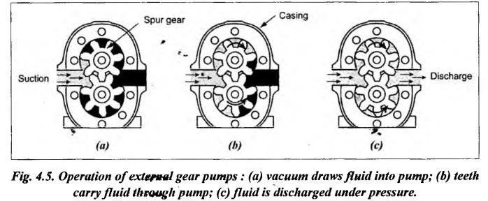
3. Analysis of Volumetric Displacement and Theoretical Flow Rate


4. Volumetric Efficiency
5. Advantages and Disadvantages of External Gear Pumps
6. Ranges of External Gear Pumps
Hydraulics and Pneumatics: Unit I: Fluid Power Priniciples and Hydraulic Pumps : Tag: : Construction, Operation, Volumetric Efficiency, Advantages and Disadvantages - External Gear Pumps
Related Topics
Related Subjects

Hydraulics and Pneumatics
ME3492 4th semester Mechanical Dept | 2021 Regulation | 4th Semester Mechanical Dept 2021 Regulation